7-20 750/760 Feeder Management Relay GE Multilin
7.4 MODBUS MEMORY MAP 7 COMMUNICATIONS
7
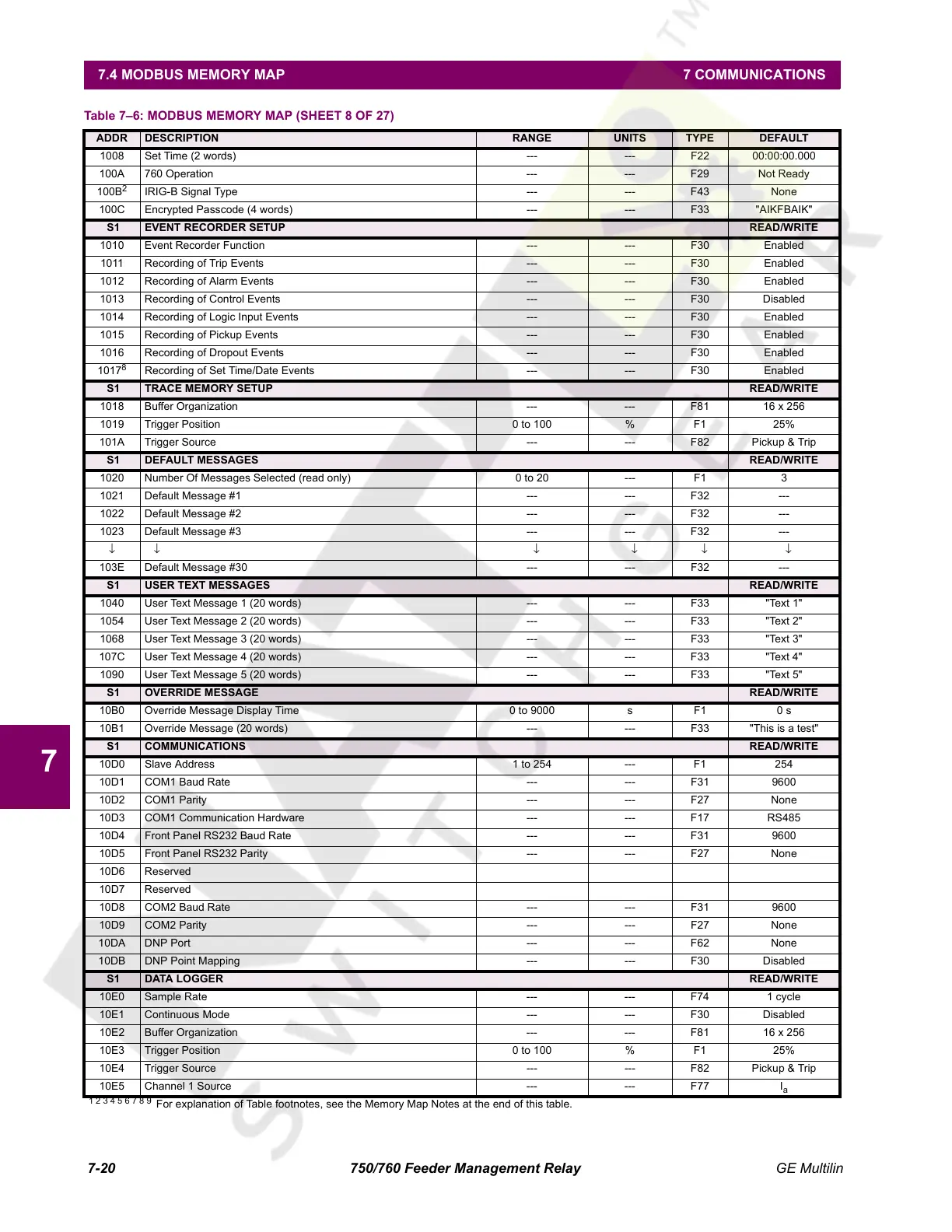
1008 Set Time (2 words) --- --- F22 00:00:00.000
100A 760 Operation --- --- F29 Not Ready
100B
2
IRIG-B Signal Type --- --- F43 None
100C Encrypted Passcode (4 words) --- --- F33 "AIKFBAIK"
S1 EVENT RECORDER SETUP READ/WRITE
1010 Event Recorder Function --- --- F30 Enabled
1011 Recording of Trip Events --- --- F30 Enabled
1012 Recording of Alarm Events --- --- F30 Enabled
1013 Recording of Control Events --- --- F30 Disabled
1014 Recording of Logic Input Events --- --- F30 Enabled
1015 Recording of Pickup Events --- --- F30 Enabled
1016 Recording of Dropout Events --- --- F30 Enabled
1017
8
Recording of Set Time/Date Events --- --- F30 Enabled
S1 TRACE MEMORY SETUP READ/WRITE
1018 Buffer Organization --- --- F81 16 x 256
1019 Trigger Position 0 to 100 % F1 25%
101A Trigger Source --- --- F82 Pickup & Trip
S1 DEFAULT MESSAGES READ/WRITE
1020 Number Of Messages Selected (read only) 0 to 20 --- F1 3
1021 Default Message #1 --- --- F32 ---
1022 Default Message #2 --- --- F32 ---
1023 Default Message #3 --- --- F32 ---
↓↓ ↓↓↓↓
103E Default Message #30 --- --- F32 ---
S1 USER TEXT MESSAGES READ/WRITE
1040 User Text Message 1 (20 words) --- --- F33 "Text 1"
1054 User Text Message 2 (20 words) --- --- F33 "Text 2"
1068 User Text Message 3 (20 words) --- --- F33 "Text 3"
107C User Text Message 4 (20 words) --- --- F33 "Text 4"
1090 User Text Message 5 (20 words) --- --- F33 "Text 5"
S1 OVERRIDE MESSAGE READ/WRITE
10B0 Override Message Display Time 0 to 9000 s F1 0 s
10B1 Override Message (20 words) --- --- F33 "This is a test"
S1 COMMUNICATIONS READ/WRITE
10D0 Slave Address 1 to 254 --- F1 254
10D1 COM1 Baud Rate --- --- F31 9600
10D2 COM1 Parity --- --- F27 None
10D3 COM1 Communication Hardware --- --- F17 RS485
10D4 Front Panel RS232 Baud Rate --- --- F31 9600
10D5 Front Panel RS232 Parity --- --- F27 None
10D6 Reserved
10D7 Reserved
10D8 COM2 Baud Rate --- --- F31 9600
10D9 COM2 Parity --- --- F27 None
10DA DNP Port --- --- F62 None
10DB DNP Point Mapping --- --- F30 Disabled
S1 DATA LOGGER READ/WRITE
10E0 Sample Rate --- --- F74 1 cycle
10E1 Continuous Mode --- --- F30 Disabled
10E2 Buffer Organization --- --- F81 16 x 256
10E3 Trigger Position 0 to 100 % F1 25%
10E4 Trigger Source --- --- F82 Pickup & Trip
10E5 Channel 1 Source --- --- F77 I
a
Table 7–6: MODBUS MEMORY MAP (SHEET 8 OF 27)
ADDR DESCRIPTION RANGE UNITS TYPE DEFAULT
1 2 3 4 5 6 7 8 9
For explanation of Table footnotes, see the Memory Map Notes at the end of this table.
Courtesy of NationalSwitchgear.com
 Loading...


