GE Multilin 750/760 Feeder Management Relay 7-21
7 COMMUNICATIONS 7.4 MODBUS MEMORY MAP
7
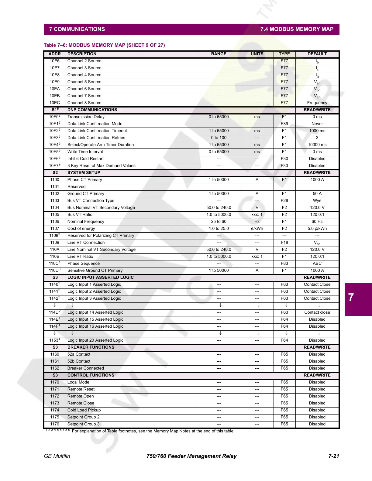
10E6 Channel 2 Source --- --- F77 I
b
10E7 Channel 3 Source --- --- F77 I
c
10E8 Channel 4 Source --- --- F77 I
g
10E9 Channel 5 Source --- --- F77 V
an
10EA Channel 6 Source --- --- F77 V
bn
10EB Channel 7 Source --- --- F77 V
cn
10EC Channel 8 Source --- --- F77 Frequency
S1
8
DNP COMMUNICATIONS READ/WRITE
10F0
8
Transmission Delay 0 to 65000 ms F1 0 ms
10F1
8
Data Link Confirmation Mode --- --- F89 Never
10F2
8
Data Link Confirmation Timeout 1 to 65000 ms F1 1000 ms
10F3
8
Data Link Confirmation Retries 0 to 100 --- F1 3
10F4
8
Select/Operate Arm Timer Duration 1 to 65000 ms F1 10000 ms
10F5
8
Write Time Interval 0 to 65000 ms F1 0 ms
10F6
8
Inhibit Cold Restart --- --- F30 Disabled
10F7
9
3 Key Reset of Max Demand Values --- --- F30 Disabled
S2 SYSTEM SETUP READ/WRITE
1100 Phase CT Primary 1 to 50000 A F1 1000 A
1101 Reserved
1102 Ground CT Primary 1 to 50000 A F1 50 A
1103 Bus VT Connection Type --- --- F28 Wye
1104 Bus Nominal VT Secondary Voltage 50.0 to 240.0 V F2 120.0 V
1105 Bus VT Ratio 1.0 to 5000.0 xxx: 1 F2 120.0:1
1106 Nominal Frequency 25 to 60 Hz F1 60 Hz
1107 Cost of energy 1.0 to 25.0 ¢/kWh F2 5.0 ¢/kWh
1108
3
Reserved for Polarizing CT Primary --- --- --- ---
1109 Line VT Connection --- --- F18 V
bn
110A Line Nominal VT Secondary Voltage 50.0 to 240.0 V F2 120.0 V
110B Line VT Ratio 1.0 to 5000.0 xxx: 1 F1 120.0:1
110C
1
Phase Sequence --- --- F83 ABC
110D
3
Sensitive Ground CT Primary 1 to 50000 A F1 1000 A
S3 LOGIC INPUT ASSERTED LOGIC READ/WRITE
1140
2
Logic Input 1 Asserted Logic --- --- F63 Contact Close
1141
2
Logic Input 2 Asserted Logic --- --- F63 Contact Close
1142
2
Logic Input 3 Asserted Logic --- --- F63 Contact Close
↓↓ ↓↓↓↓
114D
2
Logic Input 14 Asserted Logic --- --- F63 Contact close
114E
1
Logic Input 15 Asserted Logic --- --- F64 Disabled
114F
1
Logic Input 16 Asserted Logic --- --- F64 Disabled
↓↓ ↓↓↓↓
1153
1
Logic Input 20 Asserted Logic --- --- F64 Disabled
S3 BREAKER FUNCTIONS READ/WRITE
1160 52a Contact --- --- F65 Disabled
1161 52b Contact --- --- F65 Disabled
1162 Breaker Connected --- --- F65 Disabled
S3 CONTROL FUNCTIONS READ/WRITE
1170 Local Mode --- --- F65 Disabled
1171 Remote Reset --- --- F65 Disabled
1172 Remote Open --- --- F65 Disabled
1173 Remote Close --- --- F65 Disabled
1174 Cold Load Pickup --- --- F65 Disabled
1175 Setpoint Group 2 --- --- F65 Disabled
1176 Setpoint Group 3 --- --- F65 Disabled
Table 7–6: MODBUS MEMORY MAP (SHEET 9 OF 27)
ADDR DESCRIPTION RANGE UNITS TYPE DEFAULT
1 2 3 4 5 6 7 8 9
For explanation of Table footnotes, see the Memory Map Notes at the end of this table.
Courtesy of NationalSwitchgear.com
 Loading...


