7-30 750/760 Feeder Management Relay GE Multilin
7.4 MODBUS MEMORY MAP 7 COMMUNICATIONS
7
1762
3
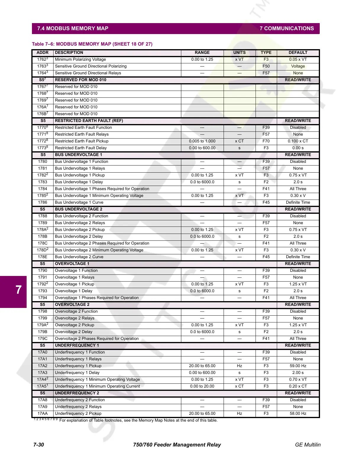
Minimum Polarizing Voltage 0.00 to 1.25 x VT F3 0.05 x VT
1763
3
Sensitive Ground Directional Polarizing --- --- F50 Voltage
1764
3
Sensitive Ground Directional Relays --- --- F57 None
S5
7
RESERVED FOR MOD 010 READ/WRITE
1767
7
Reserved for MOD 010
1768
7
Reserved for MOD 010
1769
7
Reserved for MOD 010
176A
7
Reserved for MOD 010
176B
7
Reserved for MOD 010
S5 RESTRICTED EARTH FAULT (REF) READ/WRITE
1770
8
Restricted Earth Fault Function --- --- F39 Disabled
1771
8
Restricted Earth Fault Relays --- --- F57 None
1772
8
Restricted Earth Fault Pickup 0.005 to 1.000 x CT F70 0.100 x CT
1773
8
Restricted Earth Fault Delay 0.00 to 600.00 s F3 0.00 s
S5 BUS UNDERVOLTAGE 1 READ/WRITE
1780 Bus Undervoltage 1 Function --- --- F39 Disabled
1781 Bus Undervoltage 1 Relays --- --- F57 None
1782
2
Bus Undervoltage 1 Pickup 0.00 to 1.25 x VT F3 0.75 x VT
1783 Bus Undervoltage 1 Delay 0.0 to 6000.0 s F2 2.0 s
1784 Bus Undervoltage 1 Phases Required for Operation --- --- F41 All Three
1785
2
Bus Undervoltage 1 Minimum Operating Voltage 0.00 to 1.25 x VT F3 0.30 x V
1786 Bus Undervoltage 1 Curve --- --- F45 Definite Time
S5 BUS UNDERVOLTAGE 2 READ/WRITE
1788 Bus Undervoltage 2 Function --- --- F39 Disabled
1789 Bus Undervoltage 2 Relays --- --- F57 None
178A
2
Bus Undervoltage 2 Pickup 0.00 to 1.25 x VT F3 0.75 x VT
178B Bus Undervoltage 2 Delay 0.0 to 6000.0 s F2 2.0 s
178C Bus Undervoltage 2 Phases Required for Operation --- --- F41 All Three
178D
2
Bus Undervoltage 2 Minimum Operating Voltage 0.00 to 1.25 x VT F3 0.30 x V
178E Bus Undervoltage 2 Curve --- --- F45 Definite Time
S5 OVERVOLTAGE 1 READ/WRITE
1790 Overvoltage 1 Function --- --- F39 Disabled
1791 Overvoltage 1 Relays --- --- F57 None
1792
2
Overvoltage 1 Pickup 0.00 to 1.25 x VT F3 1.25 x VT
1793 Overvoltage 1 Delay 0.0 to 6000.0 s F2 2.0 s
1794 Overvoltage 1 Phases Required for Operation --- --- F41 All Three
S5 OVERVOLTAGE 2 READ/WRITE
1798 Overvoltage 2 Function --- --- F39 Disabled
1799 Overvoltage 2 Relays --- --- F57 None
179A
2
Overvoltage 2 Pickup 0.00 to 1.25 x VT F3 1.25 x VT
179B Overvoltage 2 Delay 0.0 to 6000.0 s F2 2.0 s
179C Overvoltage 2 Phases Required for Operation --- --- F41 All Three
S5 UNDERFREQUENCY 1 READ/WRITE
17A0 Underfrequency 1 Function --- --- F39 Disabled
17A1 Underfrequency 1 Relays --- --- F57 None
17A2 Underfrequency 1 Pickup 20.00 to 65.00 Hz F3 59.00 Hz
17A3 Underfrequency 1 Delay 0.00 to 600.00 s F3 2.00 s
17A4
2
Underfrequency 1 Minimum Operating Voltage 0.00 to 1.25 x VT F3 0.70 x VT
17A5
1
Underfrequency 1 Minimum Operating Current 0.00 to 20.00 x CT F3 0.20 x CT
S5 UNDERFREQUENCY 2 READ/WRITE
17A8 Underfrequency 2 Function --- --- F39 Disabled
17A9 Underfrequency 2 Relays --- --- F57 None
17AA Underfrequency 2 Pickup 20.00 to 65.00 Hz F3 58.00 Hz
Table 7–6: MODBUS MEMORY MAP (SHEET 18 OF 27)
ADDR DESCRIPTION RANGE UNITS TYPE DEFAULT
1 2 3 4 5 6 7 8 9
For explanation of Table footnotes, see the Memory Map Notes at the end of this table.
Courtesy of NationalSwitchgear.com
 Loading...


