GE Multilin 750/760 Feeder Management Relay 7-31
7 COMMUNICATIONS 7.4 MODBUS MEMORY MAP
7
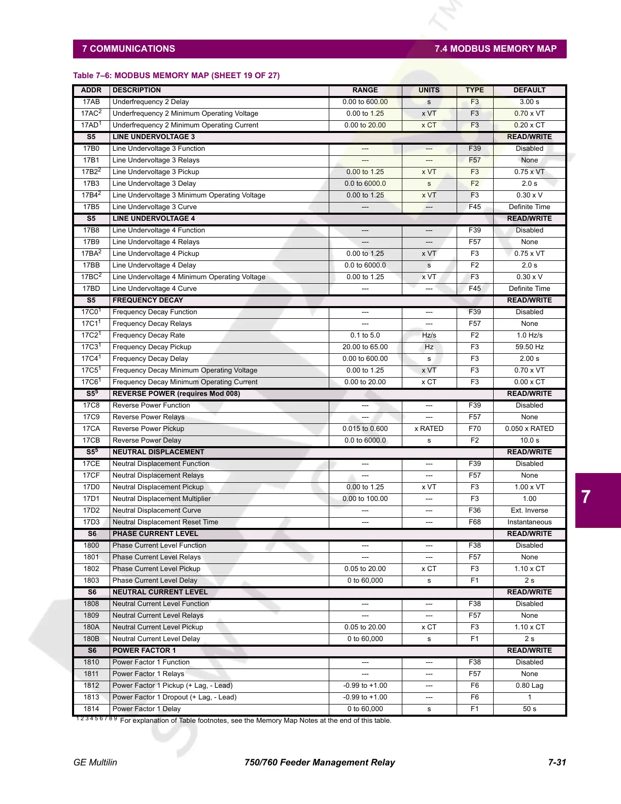
17AB Underfrequency 2 Delay 0.00 to 600.00 s F3 3.00 s
17AC
2
Underfrequency 2 Minimum Operating Voltage 0.00 to 1.25 x VT F3 0.70 x VT
17AD
1
Underfrequency 2 Minimum Operating Current 0.00 to 20.00 x CT F3 0.20 x CT
S5 LINE UNDERVOLTAGE 3 READ/WRITE
17B0 Line Undervoltage 3 Function --- --- F39 Disabled
17B1 Line Undervoltage 3 Relays --- --- F57 None
17B2
2
Line Undervoltage 3 Pickup 0.00 to 1.25 x VT F3 0.75 x VT
17B3 Line Undervoltage 3 Delay 0.0 to 6000.0 s F2 2.0 s
17B4
2
Line Undervoltage 3 Minimum Operating Voltage 0.00 to 1.25 x VT F3 0.30 x V
17B5 Line Undervoltage 3 Curve --- --- F45 Definite Time
S5 LINE UNDERVOLTAGE 4 READ/WRITE
17B8 Line Undervoltage 4 Function --- --- F39 Disabled
17B9 Line Undervoltage 4 Relays --- --- F57 None
17BA
2
Line Undervoltage 4 Pickup 0.00 to 1.25 x VT F3 0.75 x VT
17BB Line Undervoltage 4 Delay 0.0 to 6000.0 s F2 2.0 s
17BC
2
Line Undervoltage 4 Minimum Operating Voltage 0.00 to 1.25 x VT F3 0.30 x V
17BD Line Undervoltage 4 Curve --- --- F45 Definite Time
S5 FREQUENCY DECAY READ/WRITE
17C0
1
Frequency Decay Function --- --- F39 Disabled
17C1
1
Frequency Decay Relays --- --- F57 None
17C2
1
Frequency Decay Rate 0.1 to 5.0 Hz/s F2 1.0 Hz/s
17C3
1
Frequency Decay Pickup 20.00 to 65.00 Hz F3 59.50 Hz
17C4
1
Frequency Decay Delay 0.00 to 600.00 s F3 2.00 s
17C5
1
Frequency Decay Minimum Operating Voltage 0.00 to 1.25 x VT F3 0.70 x VT
17C6
1
Frequency Decay Minimum Operating Current 0.00 to 20.00 x CT F3 0.00 x CT
S5
5
REVERSE POWER (requires Mod 008) READ/WRITE
17C8 Reverse Power Function --- --- F39 Disabled
17C9 Reverse Power Relays --- --- F57 None
17CA Reverse Power Pickup 0.015 to 0.600 x RATED F70 0.050 x RATED
17CB Reverse Power Delay 0.0 to 6000.0 s F2 10.0 s
S5
5
NEUTRAL DISPLACEMENT READ/WRITE
17CE Neutral Displacement Function --- --- F39 Disabled
17CF Neutral Displacement Relays --- --- F57 None
17D0 Neutral Displacement Pickup 0.00 to 1.25 x VT F3 1.00 x VT
17D1 Neutral Displacement Multiplier 0.00 to 100.00 --- F3 1.00
17D2 Neutral Displacement Curve --- --- F36 Ext. Inverse
17D3 Neutral Displacement Reset Time --- --- F68 Instantaneous
S6 PHASE CURRENT LEVEL READ/WRITE
1800 Phase Current Level Function --- --- F38 Disabled
1801 Phase Current Level Relays --- --- F57 None
1802 Phase Current Level Pickup 0.05 to 20.00 x CT F3 1.10 x CT
1803 Phase Current Level Delay 0 to 60,000 s F1 2 s
S6 NEUTRAL CURRENT LEVEL READ/WRITE
1808 Neutral Current Level Function --- --- F38 Disabled
1809 Neutral Current Level Relays --- --- F57 None
180A Neutral Current Level Pickup 0.05 to 20.00 x CT F3 1.10 x CT
180B Neutral Current Level Delay 0 to 60,000 s F1 2 s
S6 POWER FACTOR 1 READ/WRITE
1810 Power Factor 1 Function --- --- F38 Disabled
1811 Power Factor 1 Relays --- --- F57 None
1812 Power Factor 1 Pickup (+ Lag, - Lead) -0.99 to +1.00 --- F6 0.80 Lag
1813 Power Factor 1 Dropout (+ Lag, - Lead) -0.99 to +1.00 --- F6 1
1814 Power Factor 1 Delay 0 to 60,000 s F1 50 s
Table 7–6: MODBUS MEMORY MAP (SHEET 19 OF 27)
ADDR DESCRIPTION RANGE UNITS TYPE DEFAULT
1 2 3 4 5 6 7 8 9
For explanation of Table footnotes, see the Memory Map Notes at the end of this table.
Courtesy of NationalSwitchgear.com
 Loading...


