7-32 750/760 Feeder Management Relay GE Multilin
7.4 MODBUS MEMORY MAP 7 COMMUNICATIONS
7
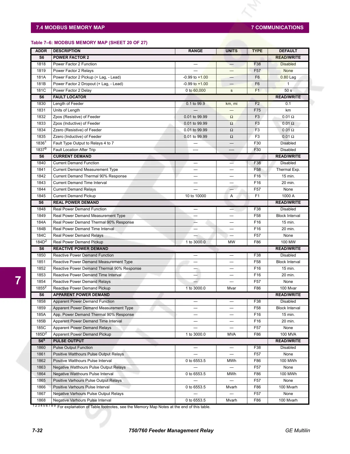
S6 POWER FACTOR 2 READ/WRITE
1818 Power Factor 2 Function --- --- F38 Disabled
1819 Power Factor 2 Relays --- --- F57 None
181A Power Factor 2 Pickup (+ Lag, - Lead) -0.99 to +1.00 --- F6 0.80 Lag
181B Power Factor 2 Dropout (+ Lag, - Lead) -0.99 to +1.00 --- F6 1
181C Power Factor 2 Delay 0 to 60,000 s F1 50 s
S6 FAULT LOCATOR READ/WRITE
1830 Length of Feeder 0.1 to 99.9 km, mi F2 0.1
1831 Units of Length --- --- F75 km
1832 Zpos (Resistive) of Feeder 0.01 to 99.99 Ω F3 0.01 Ω
1833 Zpos (Inductive) of Feeder 0.01 to 99.99 Ω F3 0.01 Ω
1834 Zzero (Resistive) of Feeder 0.01 to 99.99 Ω F3 0.01 Ω
1835 Zzero (Inductive) of Feeder 0.01 to 99.99 Ω F3 0.01 Ω
1836
1
Fault Type Output to Relays 4 to 7 --- --- F30 Disabled
1837
9
Fault Location After Trip ---- ---- F30 Disabled
S6 CURRENT DEMAND READ/WRITE
1840 Current Demand Function --- --- F38 Disabled
1841 Current Demand Measurement Type --- --- F58 Thermal Exp.
1842 Current Demand Thermal 90% Response --- --- F16 15 min.
1843 Current Demand Time Interval --- --- F16 20 min.
1844 Current Demand Relays --- --- F57 None
1845 Current Demand Pickup 10 to 10000 A F1 1000 A
S6 REAL POWER DEMAND READ/WRITE
1848 Real Power Demand Function --- --- F38 Disabled
1849 Real Power Demand Measurement Type --- --- F58 Block Interval
184A Real Power Demand Thermal 90% Response --- --- F16 15 min.
184B Real Power Demand Time Interval --- --- F16 20 min.
184C Real Power Demand Relays --- --- F57 None
184D
2
Real Power Demand Pickup 1 to 3000.0 MW F86 100 MW
S6 REACTIVE POWER DEMAND READ/WRITE
1850 Reactive Power Demand Function --- --- F38 Disabled
1851 Reactive Power Demand Measurement Type --- --- F58 Block Interval
1852 Reactive Power Demand Thermal 90% Response --- --- F16 15 min.
1853 Reactive Power Demand Time Interval --- --- F16 20 min.
1854 Reactive Power Demand Relays --- --- F57 None
1855
2
Reactive Power Demand Pickup 1 to 3000.0 Mvar F86 100 Mvar
S6 APPARENT POWER DEMAND READ/WRITE
1858 Apparent Power Demand Function --- --- F38 Disabled
1859 Apparent Power Demand Measurement Type --- --- F58 Block Interval
185A App. Power Demand Thermal 90% Response --- --- F16 15 min.
185B Apparent Power Demand Time Interval --- --- F16 20 min.
185C Apparent Power Demand Relays --- --- F57 None
185D
2
Apparent Power Demand Pickup 1 to 3000.0 MVA F86 100 MVA
S6
5
PULSE OUTPUT READ/WRITE
1860 Pulse Output Function --- --- F38 Disabled
1861 Positive Watthours Pulse Output Relays --- --- F57 None
1862 Positive Watthours Pulse Interval 0 to 6553.5 MWh F86 100 MWh
1863 Negative Watthours Pulse Output Relays --- --- F57 None
1864 Negative Watthours Pulse Interval 0 to 6553.5 MWh F86 100 MWh
1865 Positive Varhours Pulse Output Relays --- --- F57 None
1866 Positive Varhours Pulse Interval 0 to 6553.5 Mvarh F86 100 Mvarh
1867 Negative Varhours Pulse Output Relays --- --- F57 None
1868 Negative Varhours Pulse Interval 0 to 6553.5 Mvarh F86 100 Mvarh
Table 7–6: MODBUS MEMORY MAP (SHEET 20 OF 27)
ADDR DESCRIPTION RANGE UNITS TYPE DEFAULT
1 2 3 4 5 6 7 8 9
For explanation of Table footnotes, see the Memory Map Notes at the end of this table.
Courtesy of NationalSwitchgear.com
 Loading...


