GE Multilin 750/760 Feeder Management Relay 7-33
7 COMMUNICATIONS 7.4 MODBUS MEMORY MAP
7
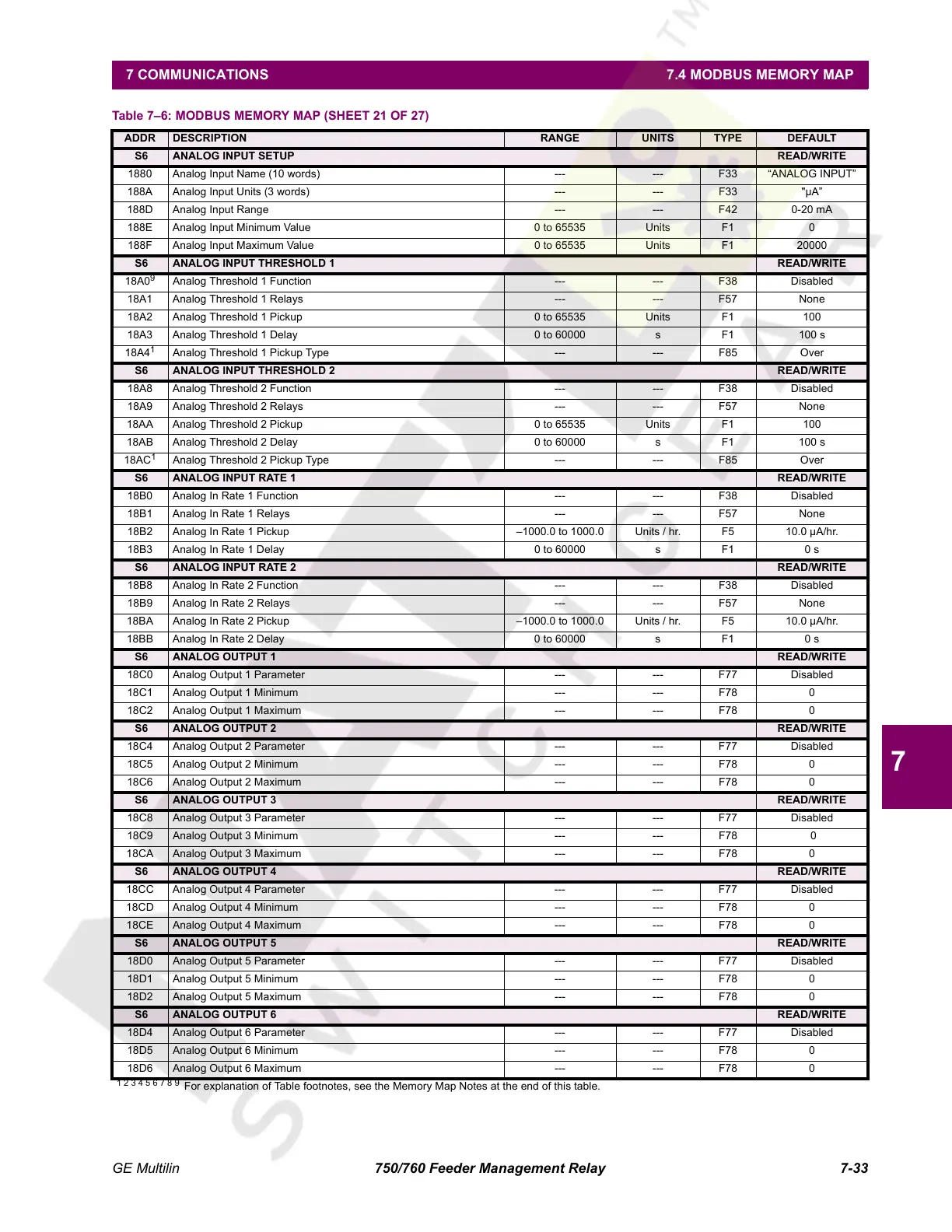
S6 ANALOG INPUT SETUP READ/WRITE
1880 Analog Input Name (10 words) --- --- F33 “ANALOG INPUT”
188A Analog Input Units (3 words) --- --- F33 "µA”
188D Analog Input Range --- --- F42 0-20 mA
188E Analog Input Minimum Value 0 to 65535 Units F1 0
188F Analog Input Maximum Value 0 to 65535 Units F1 20000
S6 ANALOG INPUT THRESHOLD 1 READ/WRITE
18A0
9
Analog Threshold 1 Function --- --- F38 Disabled
18A1 Analog Threshold 1 Relays --- --- F57 None
18A2 Analog Threshold 1 Pickup 0 to 65535 Units F1 100
18A3 Analog Threshold 1 Delay 0 to 60000 s F1 100 s
18A4
1
Analog Threshold 1 Pickup Type --- --- F85 Over
S6 ANALOG INPUT THRESHOLD 2 READ/WRITE
18A8 Analog Threshold 2 Function --- --- F38 Disabled
18A9 Analog Threshold 2 Relays --- --- F57 None
18AA Analog Threshold 2 Pickup 0 to 65535 Units F1 100
18AB Analog Threshold 2 Delay 0 to 60000 s F1 100 s
18AC
1
Analog Threshold 2 Pickup Type --- --- F85 Over
S6 ANALOG INPUT RATE 1 READ/WRITE
18B0 Analog In Rate 1 Function --- --- F38 Disabled
18B1 Analog In Rate 1 Relays --- --- F57 None
18B2 Analog In Rate 1 Pickup –1000.0 to 1000.0 Units / hr. F5 10.0 µA/hr.
18B3 Analog In Rate 1 Delay 0 to 60000 s F1 0 s
S6 ANALOG INPUT RATE 2 READ/WRITE
18B8 Analog In Rate 2 Function --- --- F38 Disabled
18B9 Analog In Rate 2 Relays --- --- F57 None
18BA Analog In Rate 2 Pickup –1000.0 to 1000.0 Units / hr. F5 10.0 µA/hr.
18BB Analog In Rate 2 Delay 0 to 60000 s F1 0 s
S6 ANALOG OUTPUT 1 READ/WRITE
18C0 Analog Output 1 Parameter --- --- F77 Disabled
18C1 Analog Output 1 Minimum --- --- F78 0
18C2 Analog Output 1 Maximum --- --- F78 0
S6 ANALOG OUTPUT 2 READ/WRITE
18C4 Analog Output 2 Parameter --- --- F77 Disabled
18C5 Analog Output 2 Minimum --- --- F78 0
18C6 Analog Output 2 Maximum --- --- F78 0
S6 ANALOG OUTPUT 3 READ/WRITE
18C8 Analog Output 3 Parameter --- --- F77 Disabled
18C9 Analog Output 3 Minimum --- --- F78 0
18CA Analog Output 3 Maximum --- --- F78 0
S6 ANALOG OUTPUT 4 READ/WRITE
18CC Analog Output 4 Parameter --- --- F77 Disabled
18CD Analog Output 4 Minimum --- --- F78 0
18CE Analog Output 4 Maximum --- --- F78 0
S6 ANALOG OUTPUT 5 READ/WRITE
18D0 Analog Output 5 Parameter --- --- F77 Disabled
18D1 Analog Output 5 Minimum --- --- F78 0
18D2 Analog Output 5 Maximum --- --- F78 0
S6 ANALOG OUTPUT 6 READ/WRITE
18D4 Analog Output 6 Parameter --- --- F77 Disabled
18D5 Analog Output 6 Minimum --- --- F78 0
18D6 Analog Output 6 Maximum --- --- F78 0
Table 7–6: MODBUS MEMORY MAP (SHEET 21 OF 27)
ADDR DESCRIPTION RANGE UNITS TYPE DEFAULT
1 2 3 4 5 6 7 8 9
For explanation of Table footnotes, see the Memory Map Notes at the end of this table.
Courtesy of NationalSwitchgear.com
 Loading...


