7-56 750/760 Feeder Management Relay GE Multilin
7.5 DNP COMMUNICATIONS 7 COMMUNICATIONS
7
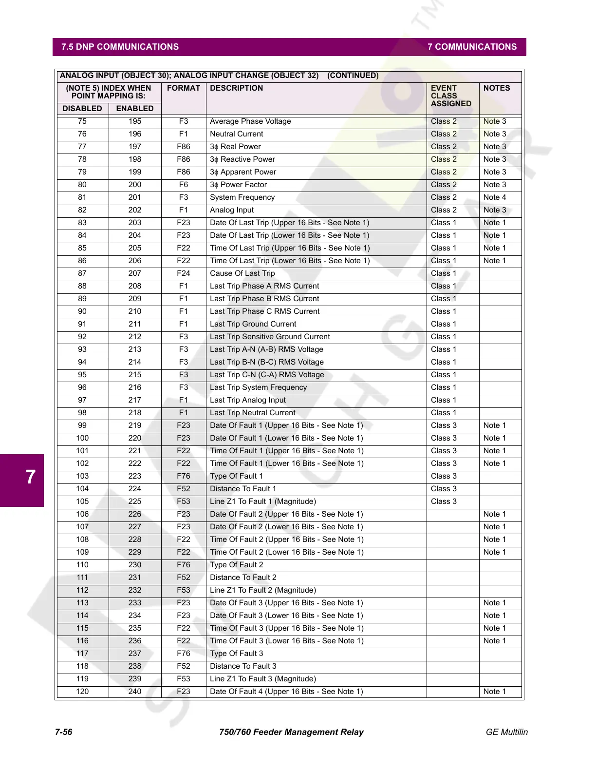
75 195 F3 Average Phase Voltage Class 2 Note 3
76 196 F1 Neutral Current Class 2 Note 3
77 197 F86 3φ Real Power Class 2 Note 3
78 198 F86 3φ Reactive Power Class 2 Note 3
79 199 F86 3φ Apparent Power Class 2 Note 3
80 200 F6 3φ Power Factor Class 2 Note 3
81 201 F3 System Frequency Class 2 Note 4
82 202 F1 Analog Input Class 2 Note 3
83 203 F23 Date Of Last Trip (Upper 16 Bits - See Note 1) Class 1 Note 1
84 204 F23 Date Of Last Trip (Lower 16 Bits - See Note 1) Class 1 Note 1
85 205 F22 Time Of Last Trip (Upper 16 Bits - See Note 1) Class 1 Note 1
86 206 F22 Time Of Last Trip (Lower 16 Bits - See Note 1) Class 1 Note 1
87 207 F24 Cause Of Last Trip Class 1
88 208 F1 Last Trip Phase A RMS Current Class 1
89 209 F1 Last Trip Phase B RMS Current Class 1
90 210 F1 Last Trip Phase C RMS Current Class 1
91 211 F1 Last Trip Ground Current Class 1
92 212 F3 Last Trip Sensitive Ground Current Class 1
93 213 F3 Last Trip A-N (A-B) RMS Voltage Class 1
94 214 F3 Last Trip B-N (B-C) RMS Voltage Class 1
95 215 F3 Last Trip C-N (C-A) RMS Voltage Class 1
96 216 F3 Last Trip System Frequency Class 1
97 217 F1 Last Trip Analog Input Class 1
98 218 F1 Last Trip Neutral Current Class 1
99 219 F23 Date Of Fault 1 (Upper 16 Bits - See Note 1) Class 3 Note 1
100 220 F23 Date Of Fault 1 (Lower 16 Bits - See Note 1) Class 3 Note 1
101 221 F22 Time Of Fault 1 (Upper 16 Bits - See Note 1) Class 3 Note 1
102 222 F22 Time Of Fault 1 (Lower 16 Bits - See Note 1) Class 3 Note 1
103 223 F76 Type Of Fault 1 Class 3
104 224 F52 Distance To Fault 1 Class 3
105 225 F53 Line Z1 To Fault 1 (Magnitude) Class 3
106 226 F23 Date Of Fault 2 (Upper 16 Bits - See Note 1) Note 1
107 227 F23 Date Of Fault 2 (Lower 16 Bits - See Note 1) Note 1
108 228 F22 Time Of Fault 2 (Upper 16 Bits - See Note 1) Note 1
109 229 F22 Time Of Fault 2 (Lower 16 Bits - See Note 1) Note 1
110 230 F76 Type Of Fault 2
111 231 F52 Distance To Fault 2
112 232 F53 Line Z1 To Fault 2 (Magnitude)
113 233 F23 Date Of Fault 3 (Upper 16 Bits - See Note 1) Note 1
114 234 F23 Date Of Fault 3 (Lower 16 Bits - See Note 1) Note 1
115 235 F22 Time Of Fault 3 (Upper 16 Bits - See Note 1) Note 1
116 236 F22 Time Of Fault 3 (Lower 16 Bits - See Note 1) Note 1
117 237 F76 Type Of Fault 3
118 238 F52 Distance To Fault 3
119 239 F53 Line Z1 To Fault 3 (Magnitude)
120 240 F23 Date Of Fault 4 (Upper 16 Bits - See Note 1) Note 1
ANALOG INPUT (OBJECT 30); ANALOG INPUT CHANGE (OBJECT 32) (CONTINUED)
(NOTE 5) INDEX WHEN
POINT MAPPING IS:
FORMAT DESCRIPTION EVENT
CLASS
ASSIGNED
NOTES
DISABLED ENABLED
Courtesy of NationalSwitchgear.com
 Loading...


