Drive shaft--Front drive shaft
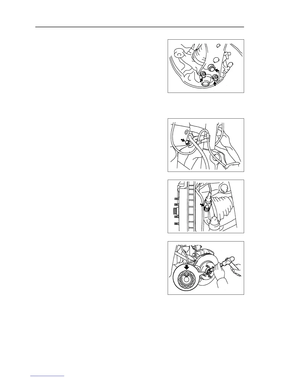
35. Assemble left lower control arm assembly [64000091]
(a) Assemble lower ball joint on lower suspension arm with the
bolts and screw caps.
Torque: 142 ± 10 N
⋅⋅
⋅⋅
⋅m
36. Assemble left transversal lever assembly.
(a) Assemble transversal lever terminal to steering knuckle with
screw cap.
Torque: 49 ± 5 N
⋅⋅
⋅⋅
⋅m
(b) Assemble new cotter pin.
Note: if hole position of cotter pin could not make a
line, lock the screw cap for 60.
37. Assemble speed sensor assembly of left front
wheels (equipping with ABS) [67000020]
(a) Assemble speed sensor absorber with bolts.
Torque: 49 ± 5 N
⋅⋅
⋅⋅
⋅m
(b) Assemble speed sensor on the steering knuckle with bolts.
Torque: 8 N
⋅⋅
⋅⋅
⋅m
Note:
z Do not damage speed sensor.
z Prevent it from contacting with sundries.
z When assembling the sensor, the wiring harness
of sensor could not bend.
38. Assemble fixing nuts of drive shaft [68000083]
(a) Assemble fixing nuts.
Torque: 216 ± 15 N
⋅⋅
⋅⋅
⋅m
(b) Use chisel and hammer to knock the fixing nuts concave
and fix them.
39. Assemble front wheels.
Torque: 103 ± 10 N
⋅⋅
⋅⋅
⋅m
40. Add the oil in gearbox.
41. Check and adjust the oil in gearbox.
42. Check and adjust wheel alignment (referring to page
87)
43. Check the ABS speed sensor (equipping with ABS).
44. Test on road.
122