Drive shaft--Left front shaft hub assembly
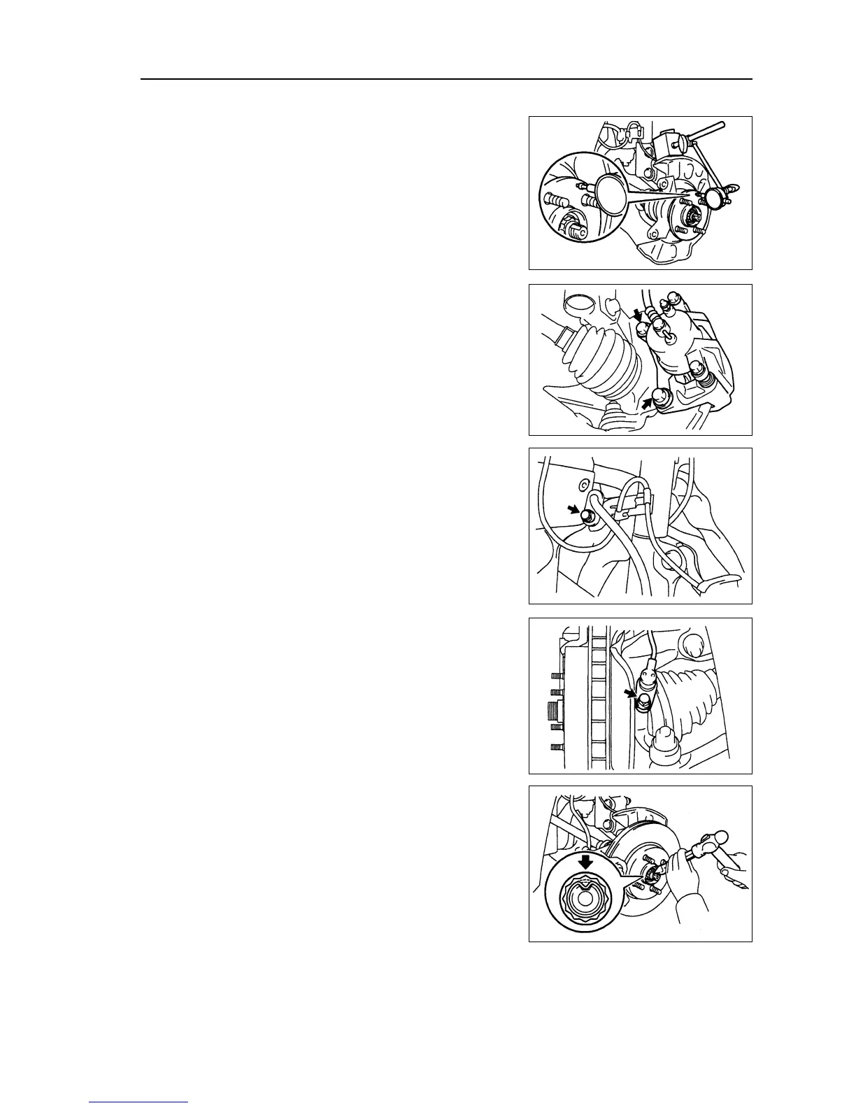
Use centimeter to check the axial clearance of shaft hub center.
Maximal value: 0.05 mm
If axial clearance exceeds the maximal value, it is necessary
to change the bearing.
28. Check the terminal face run-out of shaft hub.
Use centimeter to check the terminal run-out of exterior sur-
face of shaft hub.
Maximal value: 0.05 mm
If terminal run-out exceeds the maximal value, change the shaft
hub.
29. Assemble left front brake assembly [64000134]
30. Assemble left front brake branch pump assembly
Use two bolts to assemble brake branch pump assembly on
steering knuckle.
Torque: 106
±±
±±
± 10 N
⋅⋅
⋅⋅
⋅m
31. Assemble speed sensor assembly of left front wheel
[67000020]
(a) Assemble wiring harness of speed sensor and brake hose
on the absorber with bolts.
Torque: 29 N
⋅⋅
⋅⋅
⋅m
(b) Use the bolts to assemble speed sensor to steering knuckle.
Torque: 8.0 N
⋅⋅
⋅⋅
⋅m
Note: Do not damage the speed sensor.
z Prevent it from contacting with sundries.
z When assembling the sensor, wiring harness of sen-
sor could not bend.
32. Assemble fixing nut of left front drive shaft
[64000083]
(a) Assemble new fixing nuts,
Torque: 216
±±
±±
± 15 N
⋅⋅
⋅⋅
⋅m
(b) Use chisel and hammer to make fixing nut concave and fix
them.
33. Assemble front wheels.
Torque: 103
±±
±±
± 10 N
⋅⋅
⋅⋅
⋅m
34. Check and adjust wheel alignment (referring to page
87).
35. Check the ABS speed sensor signal.
127