2-40
Supplement
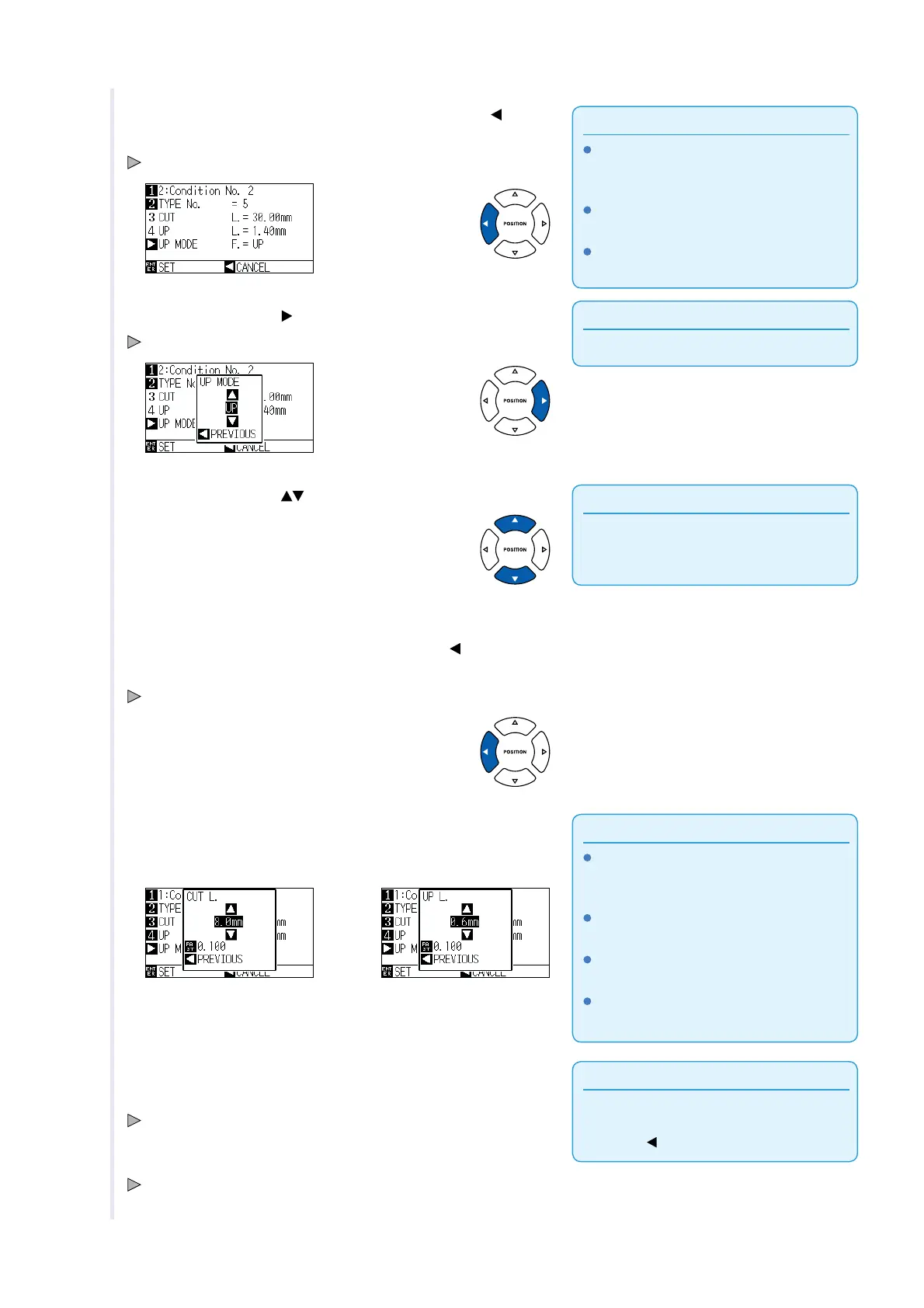
CUT L and UP L is displayed when the TYPE
No. 0-7 is selected. Also, you will be able to
set the UP MODE.
Setting for all becomes enabled when USER
is selected.
Nothing will be displayed when "NONE" or
"OFF" is selected.
9 Confirm the setting value, and press the POSITION ( ) key
(PREVIOUS).
TYPE No. is selected and return to CUT LINE PATTERN setting screen.
Supplement
Setting range is from 1 to 31, and "UP".
10 Press the POSITION ( ) key (UP MODE).
UP MODE setting screen is displayed.
Supplement
Value set here will be the cut force for the
uncut part of the perforated lines. Toll will be
raised when set to "UP".
11 Press the POSITION ( ) key and set the UP MODE.
12 Confirm the setting, and press the POSITION ( ) key
(PREVIOUS).
It will return to UP MODE CUT LINE PATTERN setting screen.
Supplement
If the TYPE No. 0 to 7 is selected in step 8, CUT
L and UP L is only displayed, and not possible
to change. Skip this step, and proceed.
Range possible to set for the CUT L is 0.1
mm to 100.0 mm.
Range possible to set for the UP L is 0.1 mm
to 10.0 mm.
Digits of settings can be changed by pressing
the [FAST] key.
13 If the "USER" is chosen in step 8, press the [3] key (CUT)
and the [4] key (UP) to set the cut length and tool up length.
Follow steps 10 to 12 for this operation.
Supplement
It will return to CONDITION screen (2/3) without
changing the settings when you press the
POSITION (
) key (CANCEL).
14 Confirm the setting and press the [ENTER] key (SET) in the
CUT LINE PATTERN setting screen.
Setting will be set, and it will return to CONDITION screen (2/3).
15 Press the [COND/TEST] key.
It will return to the default screen.