1-15-96 96-8100
HAAS AUTOMATION, INC.
101
MECHANICAL SERVICE
SERVICE
MANUAL
VF-SERIES
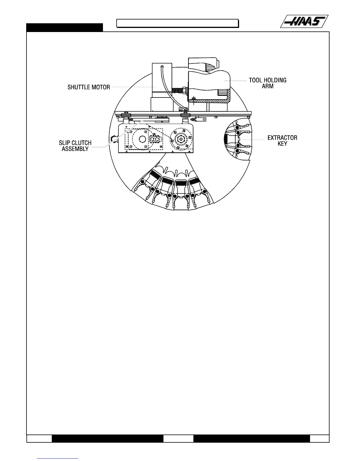
Fig. 12-3 Automatic Tool Changer - Mechanical Assembly (Top View)
4. With the extractor fork removed, inspect the alignment key mounted under the extractor. If it is
damaged due to improper spindle orientation, replace it and correct the orientation (Refer to appropriate section) after
the extractor fork has been replaced.
5. Put a drop of blue Loctite on each of the SHCS and attach the new extractor fork to the ATC with the SHCS. DO NOT
OVER-TORQUE! Ensure the distance from the edge of the extractor fork to the edge of the pocket in the carousel is the
same on both sides in accordance with the following section.
6. Test run the ATC to ensure proper operation.
12.6 SLIDING COVER REPLACEMENT
NOTE: If any of the sliding covers on the ATC do not slide freely or are bent in a crash, they must bereplaced.
1. Loosen the four screws that attach the sliding panel cover to the carousel. Be careful to not lose the spring that
holds the sliding cover closed or the number plate on the ATC carousel.
2. Inspect the cover for any galling or damage. Inspect the spring for damage.
3. Loosely install the two innermost screws that attach the number plate and the cover to the carousel and slide the
spring into position in the slot in the ATC carousel.

 Loading...


