96-8100 1-15-96
74
MECHANICAL SERVICE
HAAS AUTOMATION, INC.
SERVICE
MANUAL
VF-SERIES
5. Lower the transmission carefully to just above the spindle head. Place the drive belt onto the transmission pulley.
6. Lower the transmission into the spindle head, taking care not to crush or bind the drive belt as you lower.
7. Insert and tighten down the six SHCS attaching the transmission to the spindle head. If these screws include
gearbox isolators, ensure the following:
Ø The fender washer is placed below the 3/8" black washer when screw is installed.
Ø The 3/8" fender washer is not touching the gearbox housing.
Adjust the drive belt tension as noted in "Belt Assembly" section before tightening screws down completely.
8. Reattach the cable carrier to the solenoid bracket and reconnect all electrical and fluid lines. Replace any leaking
lines at this time, if necessary.
NOTE: The hoist must be disassembled before removing from the mill table. Break down the hoist by removing the
boom assembly, then the mast. It will not be necessary to completely break down the hoist after the first assembly.
NOTE: On shot pin assemblies that do not have a hole through the shaft, ensure the positioning ring has an adequate
layer of grease around the circumference before starting operation. On those assemblies that do have a hole through
the shaft, do not grease the orient ring.
9. AXIS MOTOR REMOVAL / INSTALLATION
PLEASE READ THIS SECTION IN ITS ENTIRETY BEFORE ATTEMPTING TO REMOVE OR REPLACE THE MOTORS.
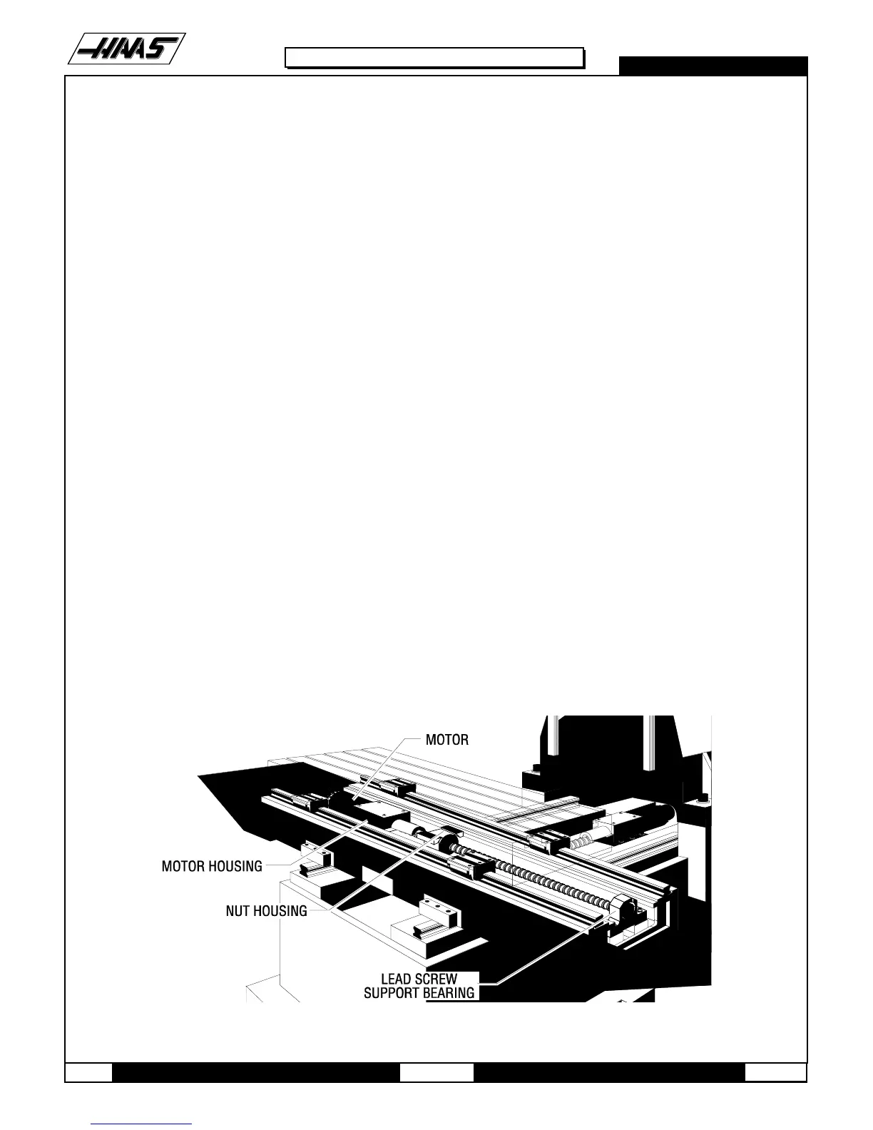
9.1 X-AXIS MOTOR REMOVAL -
1. Turn the VMC ON. ZERO RETURN all axes and put the machine in HANDLE JOG mode.
Fig. 9-1 X-axis motor and components.

 Loading...


