96-8100 1-15-96
62
MECHANICAL SERVICE
HAAS AUTOMATION, INC.
SERVICE
MANUAL
VF-SERIES
6. SPINDLE ORIENTATION
PLEASE READ THIS SECTION IN ITS ENTIRETY BEFORE ATTEMPTING TO ORIENT THE SPINDLE.
6.1 SPINDLE ORIENTATION
1. Remove cover panels from the head stock area ("Head Covers Removal"), and tool changer front cover.
2. In MDI mode, press the ORIENT SPINDLE button.
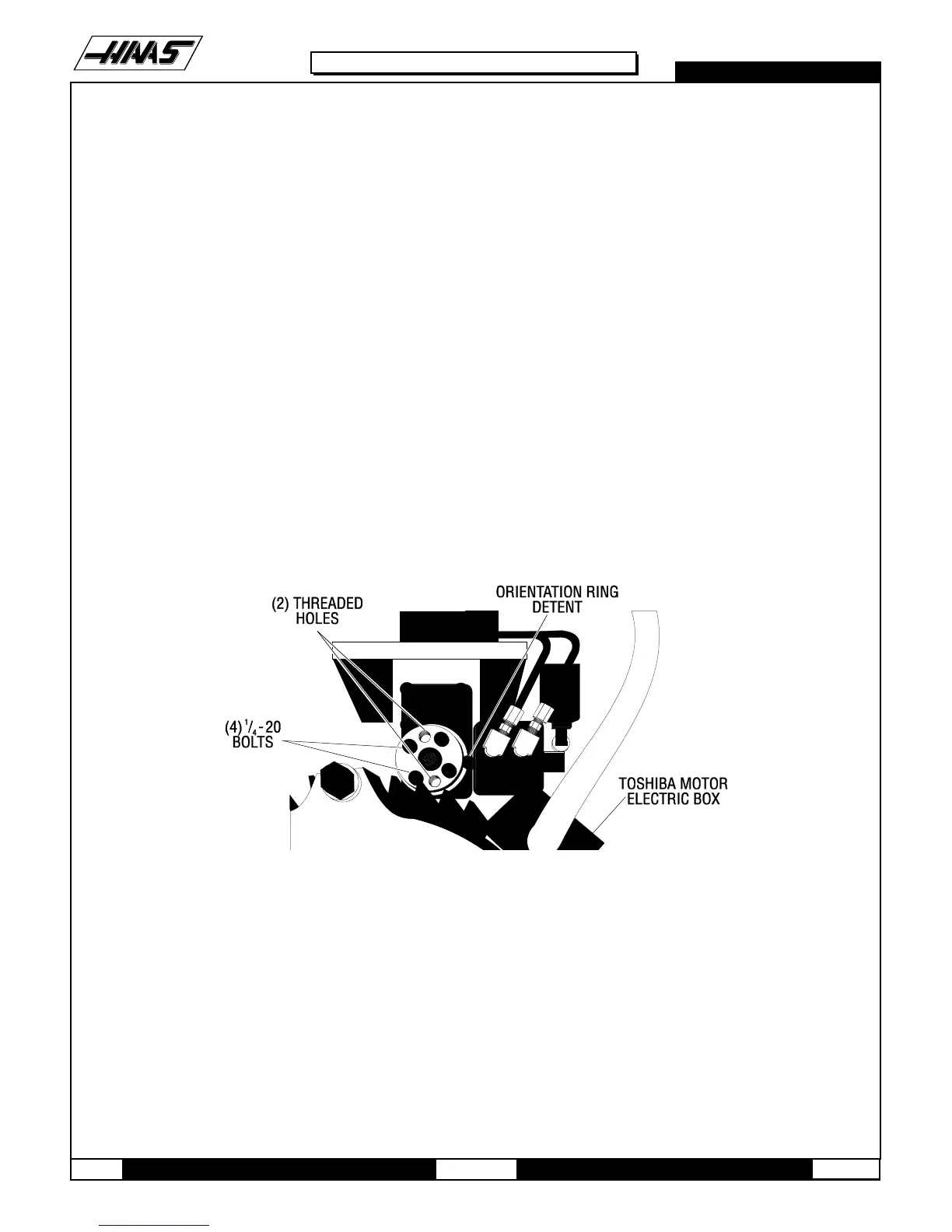
3. Loosen the four 1/4"-20 bolts on the orientation ring. Remove two of these bolts and insert them into the two
threaded holes on the ring. Evenly tighten these two bolts until the taper lock is broken.
4. Remove the two 1/4"-20 bolts and place them into their original holes. Tighten them finger tight, then 1/2 of a turn
more. Ensure that the orientation ring is snug, but not tight.
5. Set up a magnetic base with a 0.0005" indicator on the table. Zero the indicator on the spindle dog in the X- plane.
6. Jog the indicator across the spindle dogs and note the indicator reading. The spindle dogs should be parallel to the
X axis within 0.030".
Fig. 6-1 Top view of spindle orientation components.

 Loading...


