96-8100 1-15-96
142
ELECTRICAL SERVICE
SERVICE
MANUAL
VF-SERIES
HA AS AUTOMATION, INC.
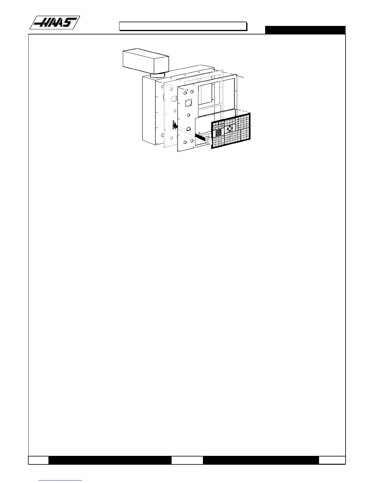
Fig. 5-4 Keypad installation.
8. Insert the ribbon cable through the opening in the control panel and place the keypad in the upper right corner of the
lower opening and press to the control panel to mount. Plug the ribbon cable into the Keyboard Interface board, taking
care to not bend the pins on the board.
9. While holding the bezel spacer in place, remove the two screws holding the spacer, put the front cover panel in place,
and fasten with all screws previously removed.
10.Reinstall all switches, spindle load meter, and the jog handle as described in the previous sections.
11.Replace the rear cover panel and fasten with the screws that were previously removed.
4.6 KEYBOARD INTERFACE
1. Follow all precautions noted previously before working in the control cabinet (See warning at beginning of Section 5).
2. Turn the main switch (upper right of electrical cabinet) to the off position.
3. Remove the four screws on the back of the control box, then remove the cover panel. Take care to hold the panel in
place until all screws have been removed.
4. Disconnect all leads to the Keyboard Interface (KBIF) board. Ensure all cables are properly labeled for reconnecting
later. Refer to Fig. 4-10 for locations.
5. After all cables have been disconnected, unscrew the four screws holding the KBIF board to the control box.
Take care to hold the board in place until all screws have been removed. Place the screws and standoffs aside for
later use.
6. Replace the KBIF board, using the four screws previously removed, starting at the top right. Attach the screw and
standoff loosely, then all other screws and standoffs, until all are mounted. Tighten down completely.

 Loading...


