96-8100 1-15-96
120
ELECTRICAL SERVICE
SERVICE
MANUAL
VF-SERIES
HA AS AUTOMATION, INC.
7. Install the new air solenoid on the air solenoid assembly. Reinstall the air solenoid assembly onto the tool release
piston assembly. Take care to not disturb the position of the clamp/unclamp switches.
8. Reinstall the tool release piston assembly (Mechanical Service).
9. Ensure all air lines are reconnected to their proper fitting!
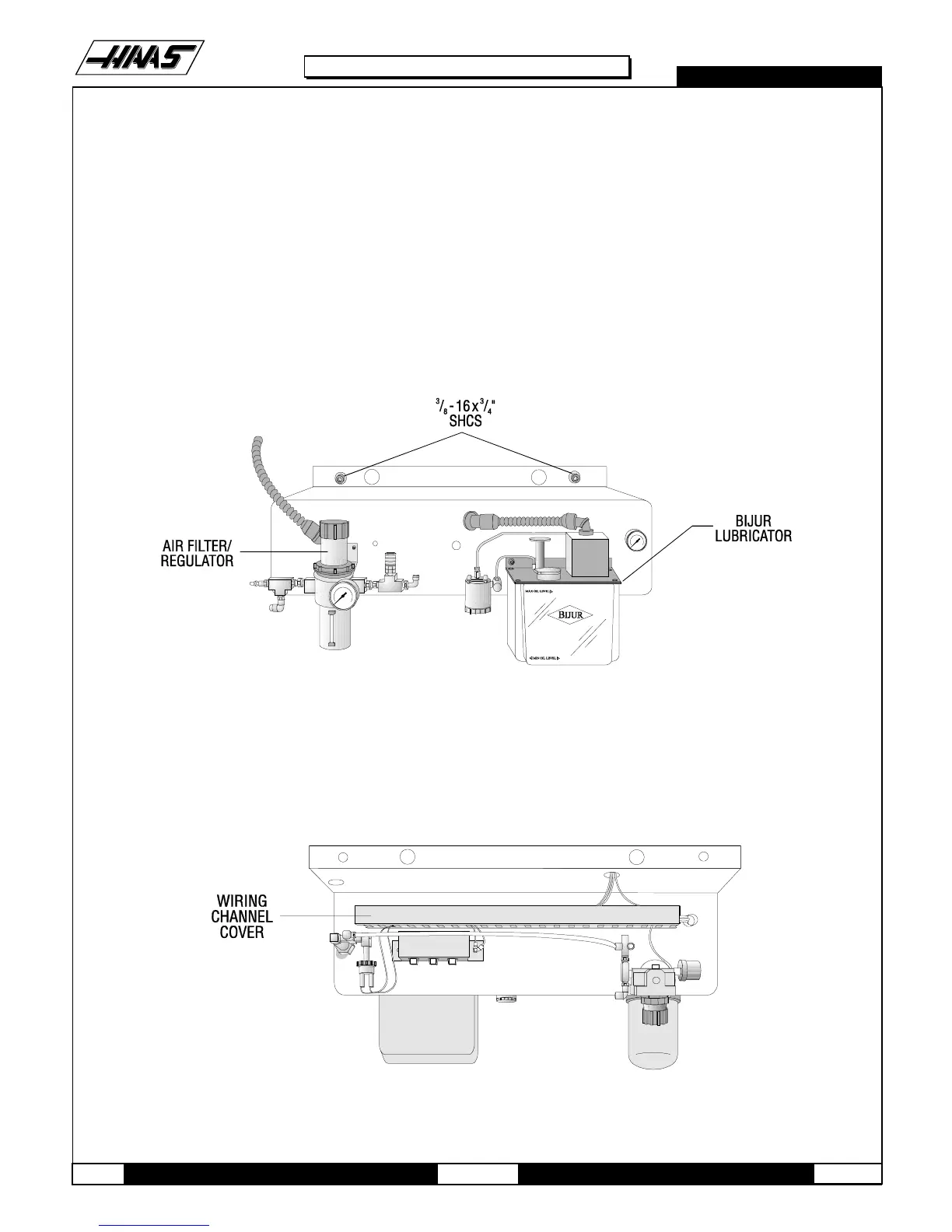
1.3 SPINDLE LUBE AIR SOLENOID
1. Turn the machine power off and remove the air supply from the machine.
Fig. 1-3 Front side of lube/air panel.
2. Disconnect the air lines from the spindle lube air solenoid assembly.
3. Unplug the electrical leads at the quick-disconnect. You will have to slide the wiring channel cover back to disconnect
the leads.
Fig. 1-4 Top view of spindle lube/air solenoid assembly.

 Loading...


