96-8100 1-15-96
44
MECHANICAL SERVICE
HAAS AUTOMATION, INC.
SERVICE
MANUAL
VF-SERIES
2 . TOOL RELEASE PISTON ASSEMBLY
PLEASE READ THIS SECTION IN ITS ENTIRETY BEFORE ATTEMPTING TO REPLACE TOOL RELEASE PISTON
ASSEMBLY.
NOTE: If machine is equipped with the TSC option, refer to the "Through the Spindle Coolant" section for TRP Assem-
bly procedures.
2.1 REMOVAL
1. Remove cover panels from the headstock area in accordance with "Head Covers Removal and Installation".
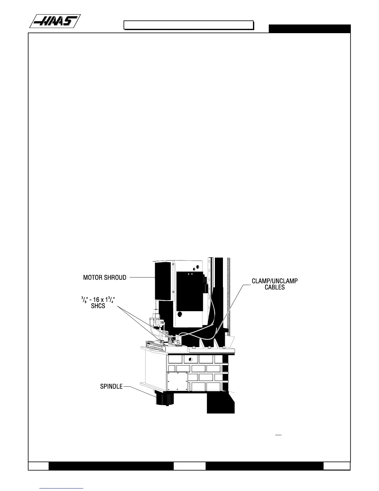
2. Remove the four 3/8-16 x 1¾" SHCS holding the tool release piston assembly to the head casting.
3. Disconnect the air line at the lube/air panel.
4. Disconnect the clamp/unclamp cables (quick disconnect) and the assembly's solenoid wiring located on the sole-
noid bracket.
5. Remove the tool release air hose at the fitting shown in Fig. 2-2.
6. Remove entire tool release piston assembly.
Fig. 2-1 Spindle and headstock area shown with covers removed. VF-0 will have no transmission.

 Loading...


