1-15-96 96-8100
125
TABLE OF CONTENTS
ELECTRICAL SERVICE
VF-SERIES
SERVICE
MANUAL
HA AS AUTOMATION, INC.
3. FUSE REPLACEMENT
PLEASE READ THIS SECTION IN ITS ENTIRETY BEFORE ATTEMPTING TO REPLACE ANY FUSES.
3.1 OVERVOLTAGE FUSES
WARNING! The electrical panel will have residual voltage, even after power has been shut off and/or disconnected . Never
work inside this cabinet until the small red CHARGE light on the servo drive assembly goes out. The servo drive assembly
is on the left side of the main control cabinet and about halfway down. This light is at the top of the circuit card at the center
of the assembly. Until this light goes out, there are dangerous voltages in the assembly EVEN WHEN POWER IS SHUT OFF.
1. T urn machine power off.
2. Turn the main switch (upper right of electrical cabinet) to the off position.
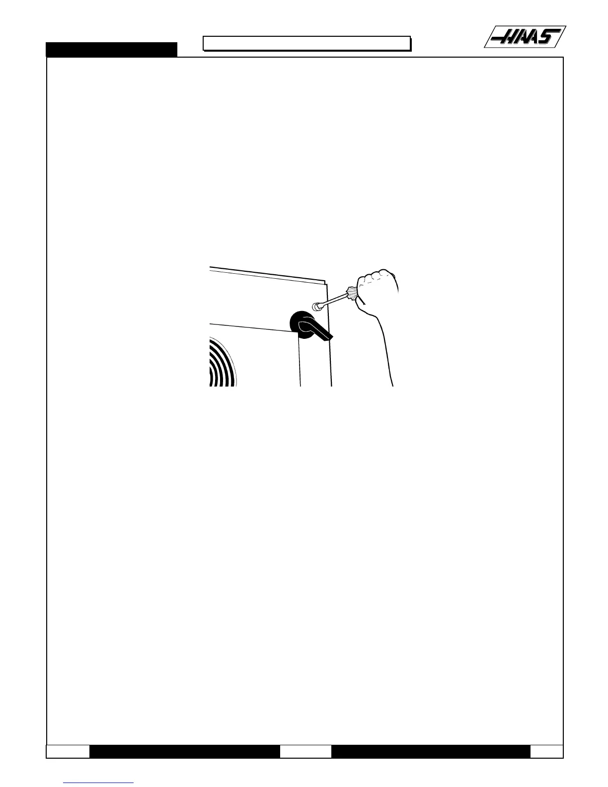
Fig. 3-1 Unscrew the three screws to open the cabinet door. (Newer control cabninets may require a key)
3. Using a large flat tip screwdriver, loosen the three screws on the cabinet door and then open the door enough to safely
work on the electrical panel. Wait until at least the red CHARGE light on the servo drive assembly goes out before
beginning any work inside the electrical cabinet.
4. On the POWER SUPPLY board there are three fuses located in a row at the upper right of the board; these are the
overvolt age fuses. An orange light will be on to indicate the blown fuse(s).
5. Using a flat tip screwdriver, turn the fuse(s) counterclockwise to remove and replace the blown fuse(s) with ones
having the same type and rating (½ amp, type AGC, 250V).
CAUTION! When the left fuse is blown, it is still possible to operate the machine, thereby making an overvoltage
situation possible. VERIFY absolute voltage to the machine does not exceed 260 volts.

 Loading...


