1-15-96 96-8100
139
TABLE OF CONTENTS
ELECTRICAL SERVICE
VF-SERIES
SERVICE
MANUAL
HA AS AUTOMATION, INC.
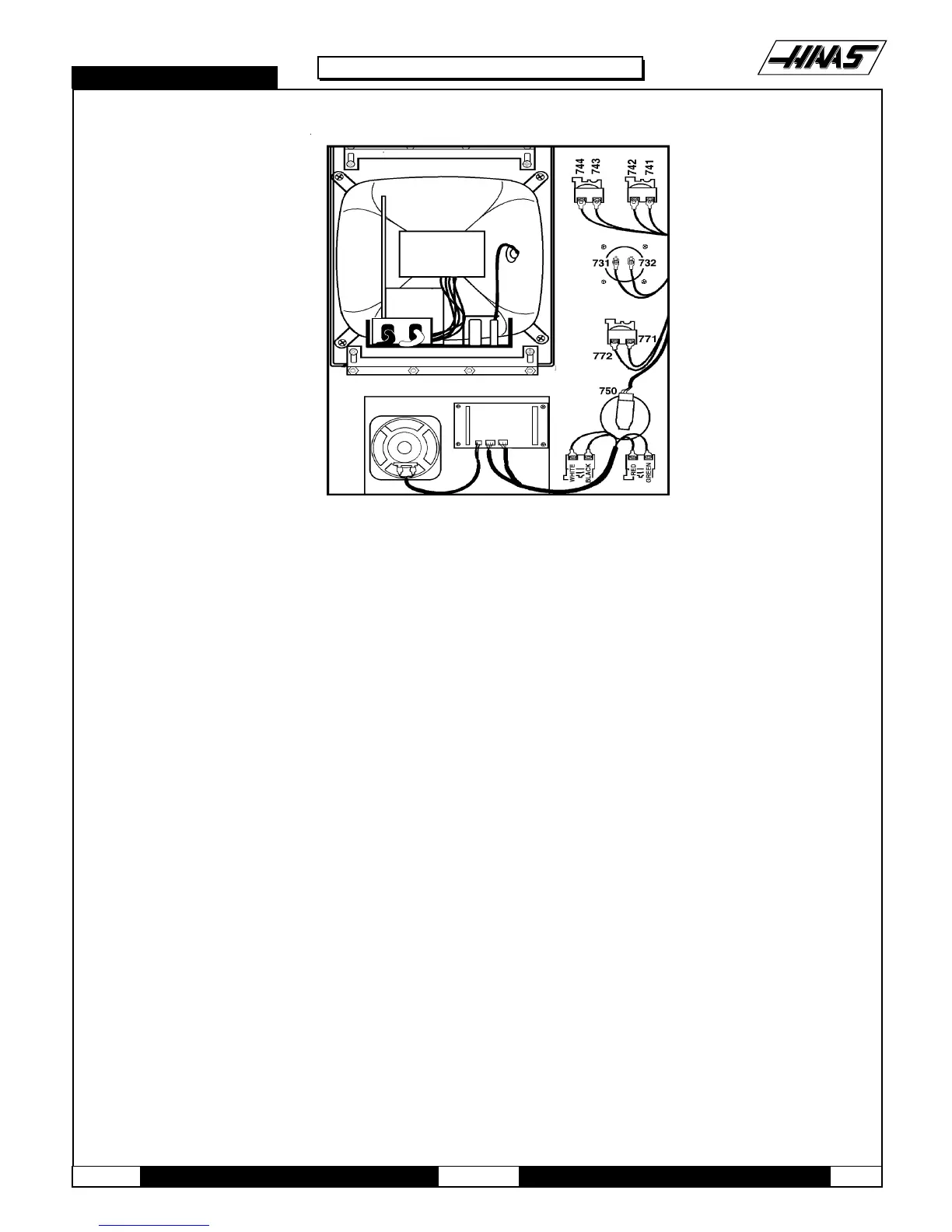
Fig. 5-1 Interior of control panel (rear).
8. Plug the black cable and white cable into the matching cables. Feed the white cable through the opening in the
top of the control panel.
9. Replace the back cover panel and attach with the four screws previously removed.
5.2 JOG HANDLE REPLACEMENT
The JOG handle is actually a 100-line-per-revolution encoder. We use 100 steps per revolution to move one of the servo
axes. If no axis is selected for jogging, turning of the crank has no effect. When the axis being moved reaches its travel
limits, the handle inputs will be ignored in the direction that would exceed the travel limits.
Parameter 57 can be used to reverse the direction of operation of the handle.
1. Turn the machine power off.
2. Remove the screws holding the cover panel on the back of the control panel. Take care to hold the cover panel in place
until all screws have been removed.
4. Unplug the cable leading to the jog handle encoder. IMPORTANT! The blank pin side of the connector must face as
shown in Fig. 5-2 when reconnecting; otherwise, damage may occur to the machine.

 Loading...


