1-15-96 96-8100
HAAS AUTOMATION, INC.
71
MECHANICAL SERVICE
SERVICE
MANUAL
VF-SERIES
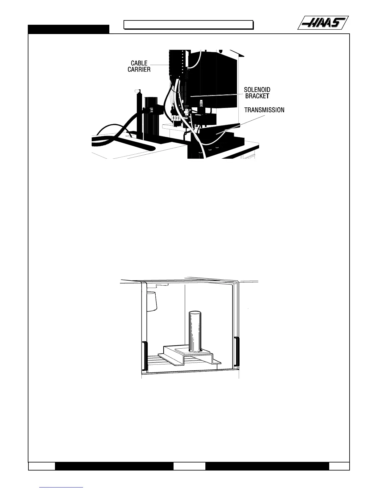
Fig. 8-6 Solenoid bracket with all lines connected.
8. Remove the two SHCS holding the cable carrier to the solenoid bracket and position the cable carrier so as to not
interfere with the transmission removal. It may be necessary to tie the cable carrier back to the Z-axis motor to keep it
in place.
9. Remove the protective cardboard from the mill table and install the support base assembly on the table, using the
four SHCS, four ½" flat washers, and the four T-nuts.
CAUTION! Ensure the protective rubber pads on the bottom of the mounting base are in place and in good condition,
or damage to the mill table may result.
Fig. 8-7 Support base/mast support assembly location.
10. With the boom modification plate in place, insert the mast into the mast support. Using the two clevis pins, attach
the boom to the mast.

 Loading...


