1-15-96 96-8100
HAAS AUTOMATION, INC.
63
MECHANICAL SERVICE
SERVICE
MANUAL
VF-SERIES
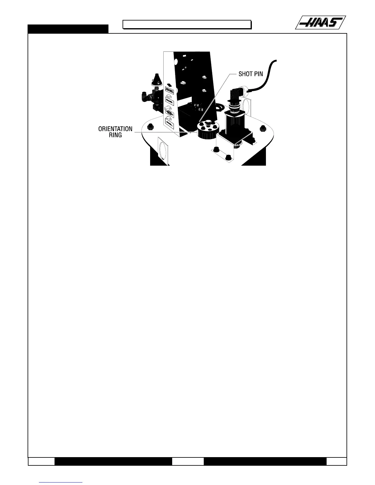
Fig. 6-2 VF-0 motor with orient ring location.
7. There is a 0.015"-0.030" backlash in the spindle system when it is oriented. Be certain to compensate for this
backlash when performing the adjustment.
8. Using a 5/8" open end wrench, rotate the spindle until the appropriate alignment is attained. If the spindle is very
difficult to rotate, STOP and return to Step 5.
9. Disconnect the main air line to the machine.
10. Manually turn the orientation ring and push the shot pin until it drops into the orient ring detent.
11. Tighten the orient screws (evenly) to 15 ft-lbs. Verify that spindle alignment has not changed.
NOTE: It is vital that the orient screws be tightened evenly. If not, the top of the orientation ring will run out and the ring
will slip.
NOTE: Ensure the orient ring has an adequate layer of grease around the circumference before starting operation.
12. Make at least 50 tool changes to test the spindle orientation.

 Loading...


