96-8100 1-15-96
94
MECHANICAL SERVICE
HAAS AUTOMATION, INC.
SERVICE
MANUAL
VF-SERIES
facilitate mounting.)
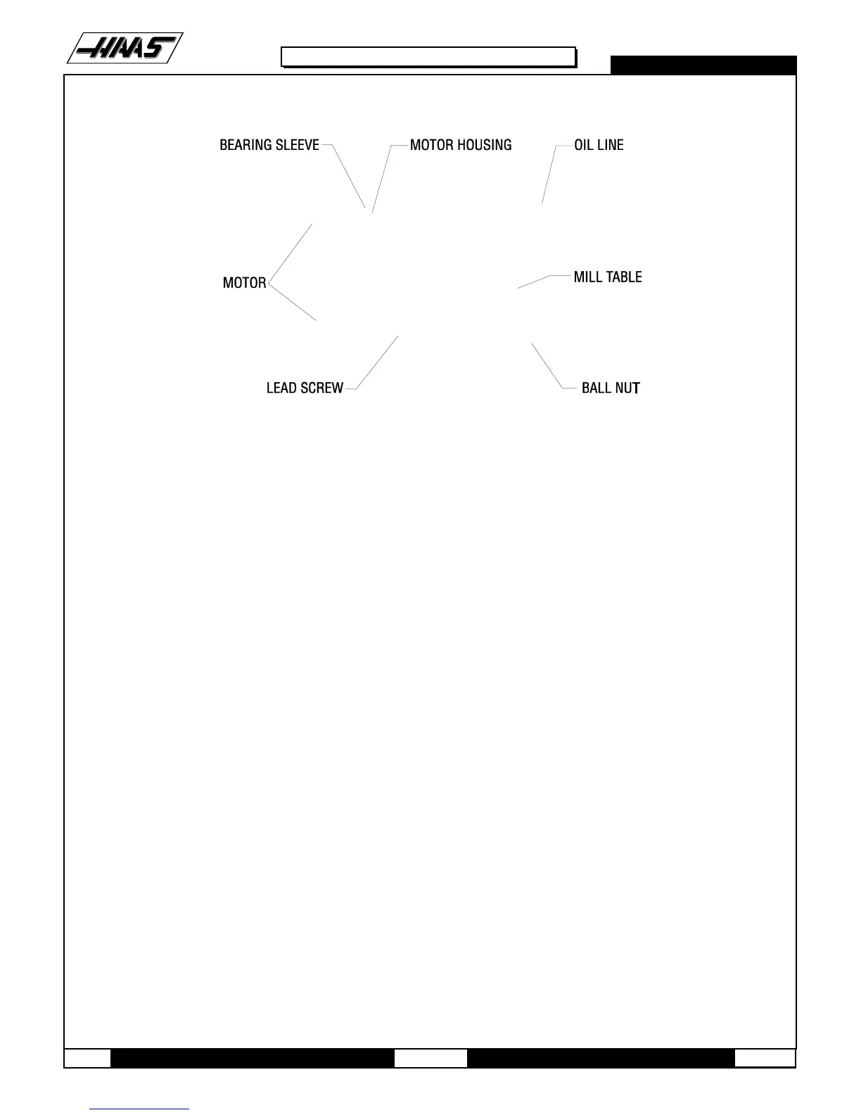
Fig 11-2 Lead screw assembly
4. Insert the six ¼-20 x 1" SHCS, attaching the bearing sleeve to the motor housing. (Place a drop of blue Loctite® on
each of the SHCS before inserting.) Tighten down completely.
5. Start the clamp nuts on both ends of the lead screw. Do not tighten.
6. Hand-turn the mill table to the far left position.
7. Loosen the six ¼-20 x 1" SHCS attaching the bearing sleeve to the motor housing and retighten completely. DO NOT
SKIP THIS STEP. It ensures the lead screw is installed and runs parallel and flat to the linear guides and the saddle.
NOTE: For the angular contact design bearing, no pre-load is necessary. Do the following:
Ø Tighten the clamp nut on the motor housing to 15 foot-pounds.
Ø Tighten the SHCS on the clamp nut.
Ø Tighten the clamp nut on the support bearing end of the lead screw until it
contacts the bearing, then tighten further approximately 1/8 of a turn.
Ø Tighten the SHCS on the clamp nut.
9. Reinstall the axis motor in accordance with "X-Axis Motor Removal".
10. Reinstall the way covers and chip tray.
11. Check for backlash in the X-axis lead screw (Troubleshooting section) or noisy operation.
11.2 Y-AXIS BEARING SLEEVE REMOVAL -
1. Turn the VMC ON. ZERO RETURN all axes and put the machine in HANDLE JOG mode.
2. Remove the axis motor in accordance with "Y-Axis Motor Removal".

 Loading...


