1-15-96 96-8100
HAAS AUTOMATION, INC.
93
MECHANICAL SERVICE
SERVICE
MANUAL
VF-SERIES
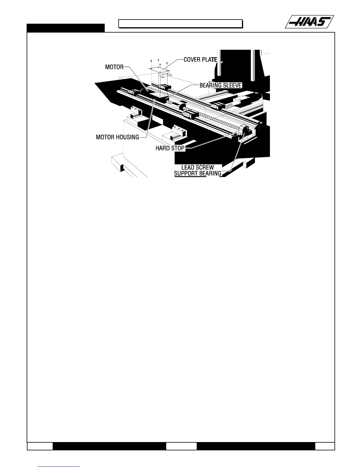
Fig. 11-1 X-axis lead screw and components.
2. Loosen the SHCS and remove the chip tray from the mill table.
3. Remove the axis motor in accordance with "X-Axis Motor Removal".
NOTE: The motor's electrical connections do not need to be removed for this operation. After removing from the motor
housing, set it to one side.
4. Loosen the 10-32 x ½" SHCS and remove the clamp nut on the lead screw in the motor housing.
5. Loosen the six ¼-20 x 1" SHCS and remove the bearing sleeve from the motor housing. Push on the mill table or the
opposite end of the lead screw to loosen.
CAUTION! DO NOT PRY THE BEARING SLEEVE AWAY FROM THE HOUSING. DAMAGE TO THE SLEEVE, BEARING, OR
LEAD SCREW WILL RESULT.
INSTALLATION -
1. Ensure all mating surfaces on the bearing sleeve, motor housing, nut housing, and ball nut are free of dirt, burrs,
grease, or other contaminants.
CAUTION! MATING SURFACES MUST BE CLEAN OR MISALIGNMENT MAY OCCUR, SERIOUSLY AFFECTING THE
PROPER OPERATION OF THE MACHINE.
2. Move mill table to the far right.
3. Place the bearing sleeve in the motor housing as shown. (It may be necessary to align the bearings in the sleeve to

 Loading...


