96-8100 1-15-96
82
MECHANICAL SERVICE
HAAS AUTOMATION, INC.
SERVICE
MANUAL
VF-SERIES
10. Slide the way cover back into place, and attach to the saddle with the 10-32x3/8" SHCS.
11. Check for backlash in Z-axis lead screw (Troubleshooting section), or noisy operation.
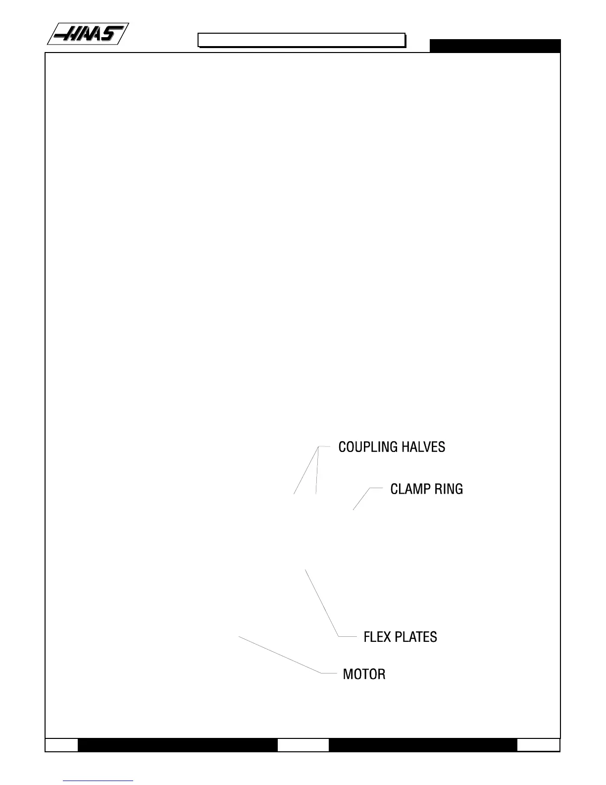
9.4 COUPLING REPLACEMENT
1. Remove the axis motor in accordance with "Axis Motor Removal/Installation" section.
NOTE: It will not be necessary at this time to completely remove the motor. Do not disconnect the electrical compo-
nents.
2. Completely loosen the 10-32 x ½" SHCS on the two coupling rings and remove the coupling.
3. For installation: Slide the new coupling onto the motor shaft until the coupling half is flush to the end of the shaft.
NOTE: Make sure that the collar split and coupling half split do not line up. Otherwise, the coupling will not be locked
tightly to the lead screw.
4. Tighten the two 10-32 x ½" SHCS on the coupling's clamp ring. Before tightening, add one drop of blue Loctite® to
each screw.
5. Reinstall the axis motor.
Fig. 9-7 Motor coupling.
10. LEAD SCREW REMOVAL AND INSTALLATION

 Loading...


