1-15-96 96-8100
HAAS AUTOMATION, INC.
81
MECHANICAL SERVICE
SERVICE
MANUAL
VF-SERIES
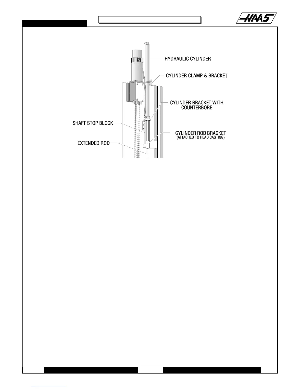
Fig. 9-6 Z-axis motor and components for machines equipped with hydraulic counterbalance.
8. Loosen the SHCS on the motor coupling at the lead screw.
9. On the motor housing, loosen the four SHCS and remove the motor from the housing.
10. Disconnect the Z-axis connection from the control panel.
INSTALLATION -
1. Slide motor into motor housing, inserting the end of the lead screw in the motor coupling.
2. Replace and tighten down the four 5/16-18 x 1¼" SHCS that hold the motor to the housing.
3. Visually inspect the flex plates to ensure that they are parallel to the coupling halves, and that the slits in the coupling
and clamp ring are in alignment (See Fig. 10-2). Tighten the 10-32 x ½" SHCS on the motor coupling at the lead screw.
(Place a drop of blue Loctite® on the screw before inserting.)
4. Replace the cover plate and fasten with the four BHCS.
5. Reconnect electrical power.
6. Remove shaft stop, if necessary.
7. If the front way cover was removed, slide it back into position, and replace the 10-32x3/8" SHCS that holds it to the
saddle.
8. Move the table to the fully forward position. Replace the rear way cover.
9. Replace the two roller brackets onto the base.

 Loading...


