96-8100 1-15-96
48
MECHANICAL SERVICE
HAAS AUTOMATION, INC.
SERVICE
MANUAL
VF-SERIES
3. BELT ASSEMBLY
PLEASE READ THIS SECTION IN ITS ENTIRETY BEFORE ATTEMPTING TO REPLACE THE DRIVE BELT.
3.1 BELT REMOVAL
NOTE: FOR EASIER REMOVAL, PLACE TRANSMISSION IN HIGH GEAR BEFORE BEGINNING.
1. Remove cover panels from headstock area in accordance with "Head Covers Removal and Installation".
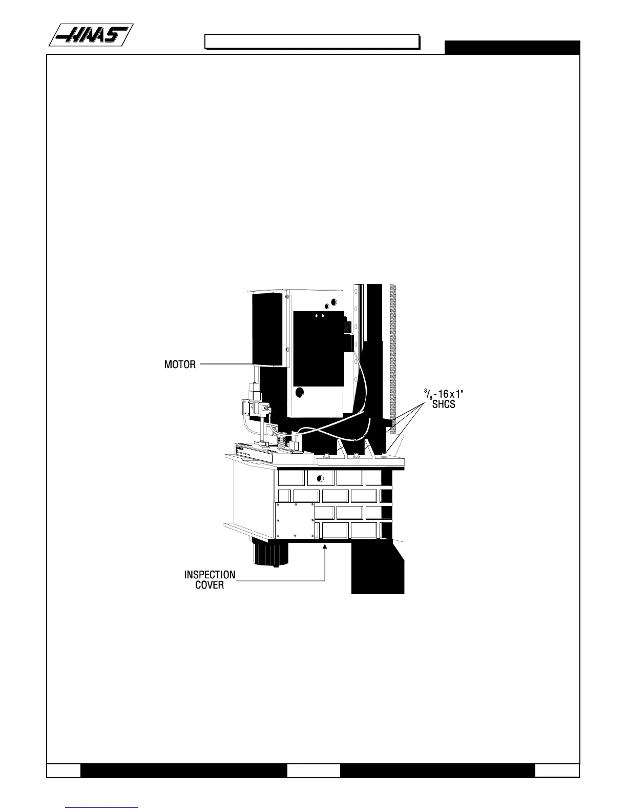
Fig. 3-1 Spindle head casting disconnect points
2. Remove tool release piston assembly in accordance with "Tool Release Piston Assembly Removal".
3. For all VMC's except VF-0, remove the six SHCS holding the transmission to the head casting and pull the transmis-
sion forward enough (½" to ¾" max.) to allow the drive belt to be pulled upward over the spindle pulley.
4. For the VF-0, remove the four SHCS holding the mounting plate to the spindle head casting. Slide the assembly
forward enough to allow the drive belt to be pulled up over the spindle pulley.

 Loading...


