96-8100 1-15-96
144
ELECTRICAL SERVICE
SERVICE
MANUAL
VF-SERIES
HA AS AUTOMATION, INC.
2. Remove head covers (Mechanical Service).
3. Disconnect the encoder cable at the top of the encoder.
4. Unscrew and remove the four 10-32 screws holding the encoder to the four standoffs (VF-1, VF-2, VF-3,VF-4) or
mount ing bracket (VF-0). Remove the encoder, leaving the belt on the pulley at the orient ring.
INSTALLATION -
If you wish to install an encoder on a machine start at step 5; if this is just a replacement, skip to step 13. Please note the
differences in installation between the VF-0, VF-1, VF-2, and the VF-3,VF-4.
5. For the VF-1, VF-2, and VF-3, VF-4, put some blue Loctite on the threads of the four set screws and screw
approximately halfway into the standoffs. Screw the hex end of the set screws into the standoffs.
6. Screw the standoffs into the four holes located at the rear of the transmissions top plate.
7. For the VF-0, place the mounting bracket in place. Fasten to the top plate with the four screws and four lock washers.
8. Place the 18-tooth pulley onto the pulley bushing and tighten down. Place the SHCS through the center axis of the
pulley.
9. Screw this assembly into the spindle orientation ring.
Fig. 6-1 Spindle encoder installation (VF-1/VF-2).
10.Place the 36-tooth pulley onto the encoder, making the top of the pulley flush with the end of the shaft.
Tighten down with the 5/64" hex wrench.
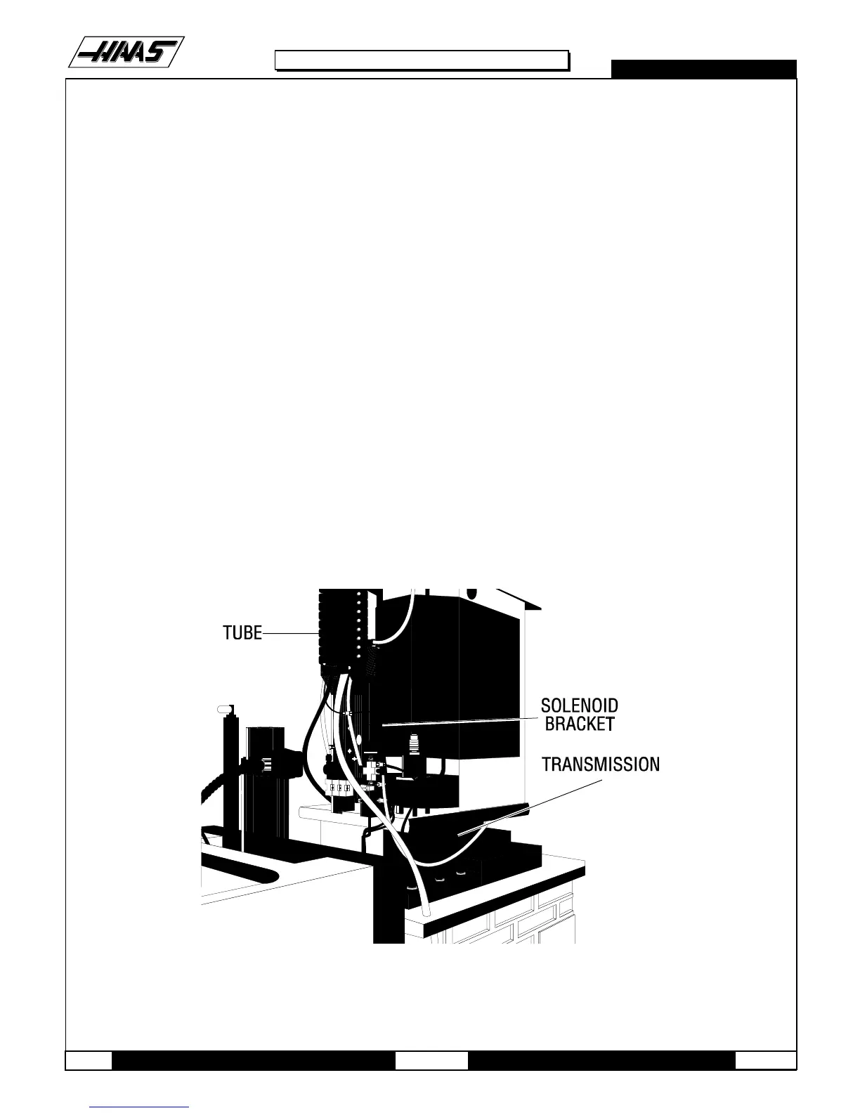
11.Unscrew the four screws and remove the cover panel on the box at the base of the flexible tube.

 Loading...


