1-15-96 96-8100
HAAS AUTOMATION, INC.
73
MECHANICAL SERVICE
SERVICE
MANUAL
VF-SERIES
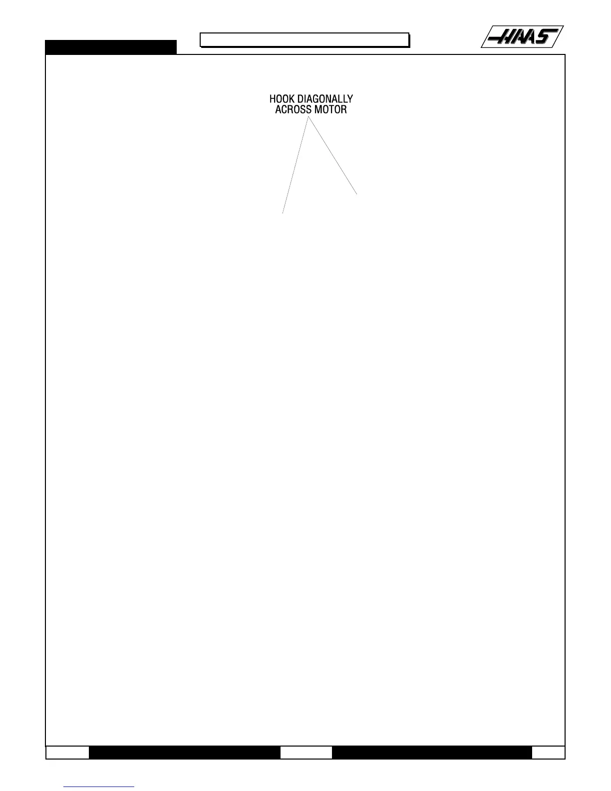
Fig. 8-10 Lifting position for VF-1 through 4.
13. For VF-1-4: Place the hoist hook in the bar's lifting eye and place the two hooks on either end of the bar into
diagonally opposite lifting holes in the motor shroud. Lift just enough to ensure the hooks are seated properly, then
carefully lift the motor and transmission assembly up enough to clear the VMC. Swing the boom toward the front of the
machine and lower onto the wood blocks.
8.5 TRANSMISSION INSTALLATION
1. If machine is equipped with Through the Spindle Coolant option, reinstall the pressure regulator, check valve
assembly, and bracket. Install two cable ties on the replacement transmission as follows:
Ø Place one cable tie around the limit switch cable.
Ø Place the second cable tie through the first one, forming a loop.
Ø Tighten the first cable tie. NOTE: The loop of the second cable tie must allow the drain line to slip through.
2. Place cradle under new transmission and lift just enough to put tension on the cables.
3. Ensure new transmission is seated securely and lift. Only lift high enough to clear the enclosure and to swing into
place.
4. Slowly swing boom around to center the cradle and transmission over the spindle head.
NOTE: Inspect the gearbox isolators to ensure the spacer is flush with the bushing on the underside of the housing.

 Loading...


