1-15-96 96-8100
HAAS AUTOMATION, INC.
115
MECHANICAL SERVICE
SERVICE
MANUAL
VF-SERIES
bracket counterbore.
8. Orient cylinder body with hydraulic hose facing away from lead screw.
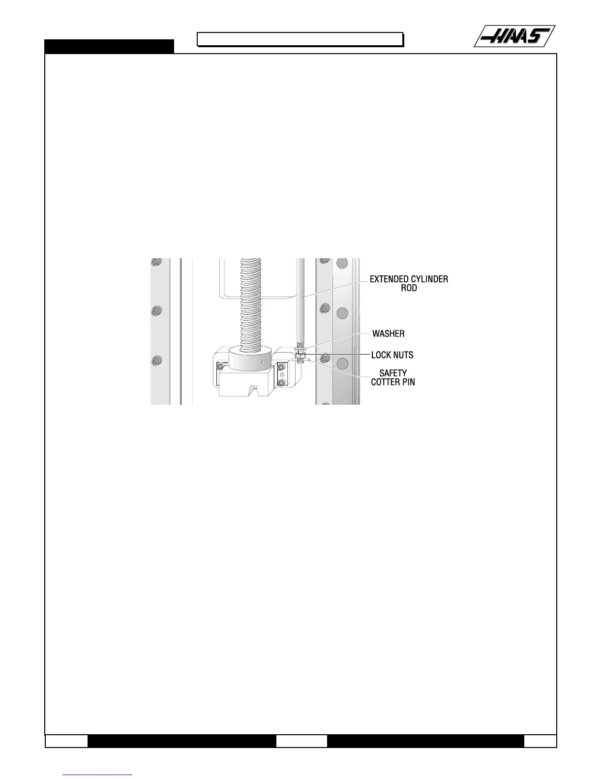
9. Install lock nuts, at threaded end of cylinder rod, wrench tight. Install safety cotter pin.
10. Install the hydraulic tank as described in the previous section, but DO NOT power up the machine.
11. Power on the machine and zero return (ZERO RET) Z-axis only. Observe cylinder body for motion or abnormal
noises. Check for fluid at manifold, cylinder hose connection and cylinder rod. Verify tank pressure at top of travel.
Remove charging system and replace valve cap.
12. Install cylinder clamp with two SHCS and bracket at top of column with bracket screw.
Fig. 15-2 Hydraulic Cylinder Rod Installation.
13. Zero return (ZERO RET) machine. HANDLE JOG Z-axis in 0.1 increments. Verify full Z travel.
14. Cycle Z-axis, using the following program, for five minutes and check for oil leaking at top of cylinder and cylinder
rod.
G28, G54, Z-14.
M99
50% Rapid
15. If Z-axis overcurrents alarm during travel, verify and correct system pressure.
NOTE:
Ø If Z-axis overcurrent alarm at top or bottom of travel, call HAAS Automation Service
Department immediately for assistance.
Ø If fluid leaks from hydraulic fittings, check that fittings are tight.
Ø If leaking continues, call HAAS Automation Service Department for assistance.
16. Reinstall Z-axis way cover with three SHCS that hold it to the spindle head.

 Loading...


