1-15-96 96-8100
129
TABLE OF CONTENTS
ELECTRICAL SERVICE
VF-SERIES
SERVICE
MANUAL
HA AS AUTOMATION, INC.
R54
980/ 1020 730B
ADDRESS BUSS DATA BUSS
550 / P10
750 / P18
660 / P6
670 / P7
680 / P8
690 / P9
990/ 1000 / P20
860 / P15
610 / P2
620 / P3
630 / P4
640 / P5
720 / P16
540 / P14
530 / P13
520 / P12
510 / P11
LOW VOLTAGE
X DRIVE
SIGNAL
Y DRIVE
SIGNAL
Z DRIVE
SIGNAL
A DRIVE
SIGNAL
SP SPEED CMD
I/O RELAYS
K25-32
I/O RELAYS
K17-24
I/O RELAYS
K9-16
I/O RELAYS
K1-8
SP DRIVE LOAD
SP TEMP
MOTIF INPUTS /
I/O OUTPUTS
JOG INFO
X ENCODER OUTPUT
Y ENCODER OUTPUT
Z ENCODER OUTPUT
A ENCODER OUTPUT
HOME SENSORS
SP ENCODER OUTPUT
P24
P17 P21 P22
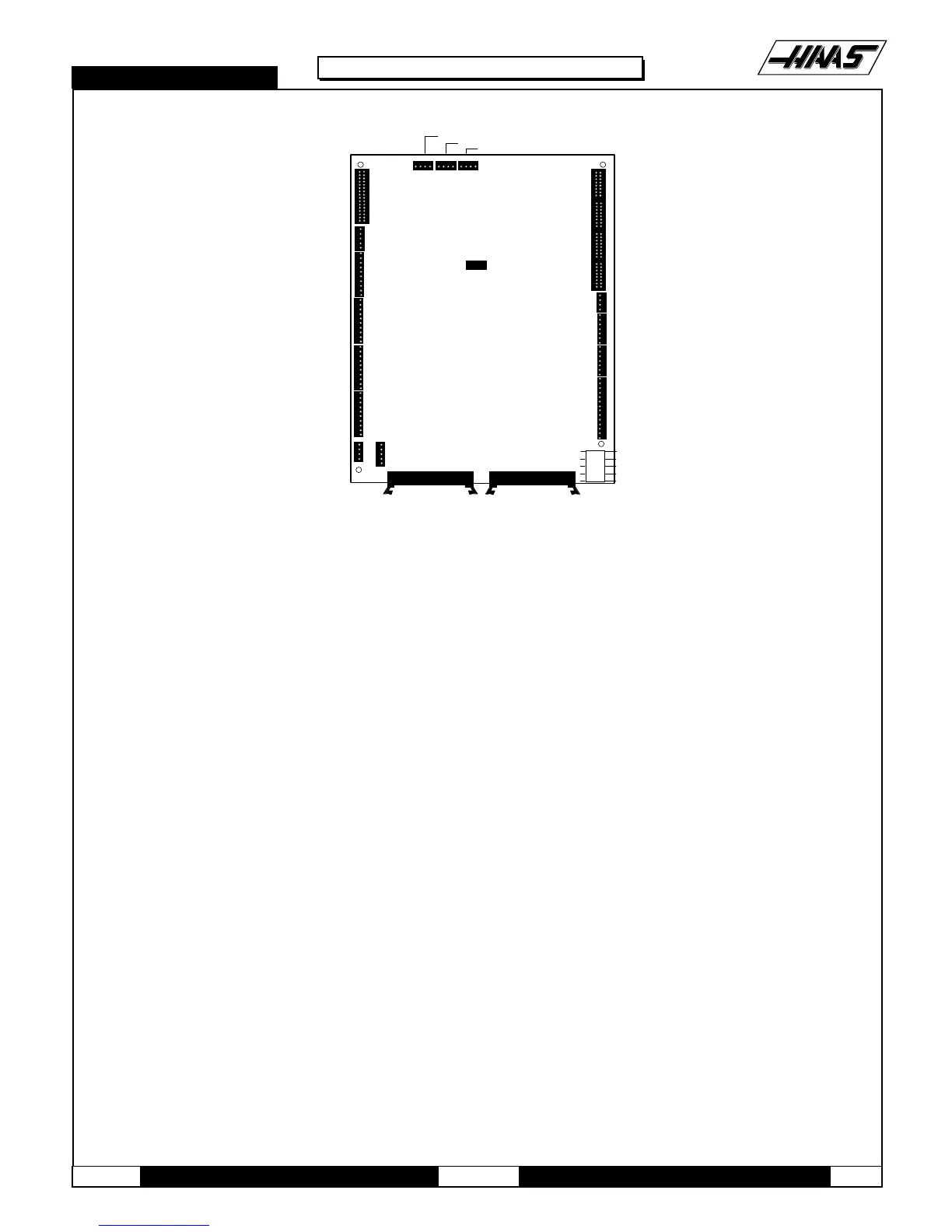
Fig. 4-1 Motor Interface board.
VIDEO BOARD AND KEYBOARD -
8. Remove the MOTIF board as described in steps 1-5.
9. Disconnect all leads to the Video board and Keyboard. Ensure all cables are properly labeled for reconnecting later.
The
following illustration shows all cable numbers and the locations on the Video and Keyboard.
10.After all cables have been disconnected, unscrew the standoffs, taking care to hold the board in place until all standoffs
have been removed.

 Loading...


