1-15-96 96-8100
165
TABLE OF CONTENTS
TECHNICAL REFERENCE
SERVICE
MANUAL
VF-SERIES
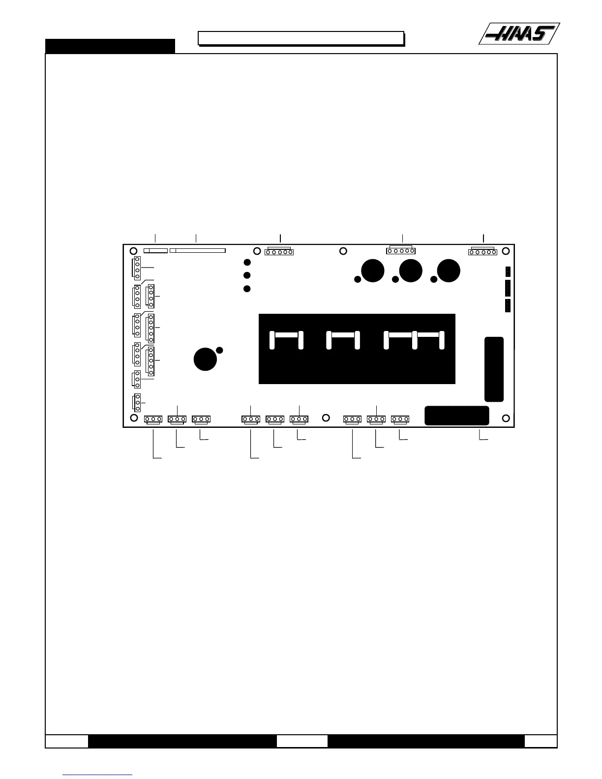
11. POWER SUPPLY ASSEMBLY
All power to the control passes through the power supply assembly. It is located on the upper right corner of the control
cabinet.
11.1 MAIN CIRCUIT BREAKER CB1
Circuit breaker CB1 is rated at 30 amps and is used to protect the spindle drive and to shut off all power to the control. The
locking On/Off handle on the outside of the control cabinet will shut this breaker off when it is unlocked. A trip of this breaker
indicates a SERIOUS overload problem and should not be reset without investigating the cause of the trip. These 30 amps
could correspond to as much as 15 horsepower.
P1
P5290 / P19
FU1 FU2 FU3
170/P4
740
P3
94
95
96
919293
70/P15800A/P14910/P7P24
860A/P17
860A/P31 90/P8 800/P30 930/P6
TB2
TB1
860/P13
860/P12
860/P27
860/P11
P26
860/P10
P9
P21
P22
FU6
CB2CB3CB4
-12V
+12V
+5V
LOW VOLTAGE
LOW VOLTAGE
LOW VOLTAGE
LOW VOLTAGE
LOW VOLTAGE
I/O +12V
+12V
SPARE
115VAC/T1
115VAC CB/SOLENOID
12VAC/OP LAMP
OP LAMP TO SWITCH
230VAC/COOLANT PUMP
230VAC/K1 CONTACTORS
115VAC OUT
115VAC IN
K1 COIL
POWER ON/OFF
AUTO OFF
230VAC/T4 190-260VAC INPUT
PRI-SEC/T5
LOW VOLTAGE
LOW VOLTAGE
SERIAL PORT 1 (-12V)
SERIAL PORT 2 (-12V)
SOLENOID COOLANT PUMP MAIN TRANSFORMER
. . . . . . . . . . . . . . . . .
FROM LVPS/P1
TO LVPS/P2
Figure 11-1 Power Supply PCB.
11.2 MAIN CONTACTOR K1
Main contactor K1 is used to turn the control on and off. The POWER ON switch applies power to the coil of K1 and after it
is energized, an auxiliary switch on K1 continues to apply power to the coil. The POWER OFF switch on the front panel will
always remove power from this contactor.
When the main contactor is off, the only power used by the control is supplied through two ½ amp fuses to the circuit that
activates the contactor. An overvoltage or lightning strike will blow these fuses and shut off the main contactor.
The power to operate the main contactor is supplied from a 24V AC control transformer that is primary fused at ½ amp. This
ensures that the only circuit powered when the machine is turned off is this transformer and only low voltage is present at the
front panel on/off switches.
11.3 LOW VOLTAGE POWER SUPPLY
The low voltage power supply provides +5V DC, +12V DC, and -12V DC to all of the logic sections of the control. It operates
from 115V AC nominal input power. It will continue to operate correctly over a 90V AC to 133V AC range.

 Loading...


