1-15-96 96-8100
HAAS AUTOMATION, INC.
77
MECHANICAL SERVICE
SERVICE
MANUAL
VF-SERIES
9. Disconnect the limit switch connection and the Y-axis connection at the side of the control panel.
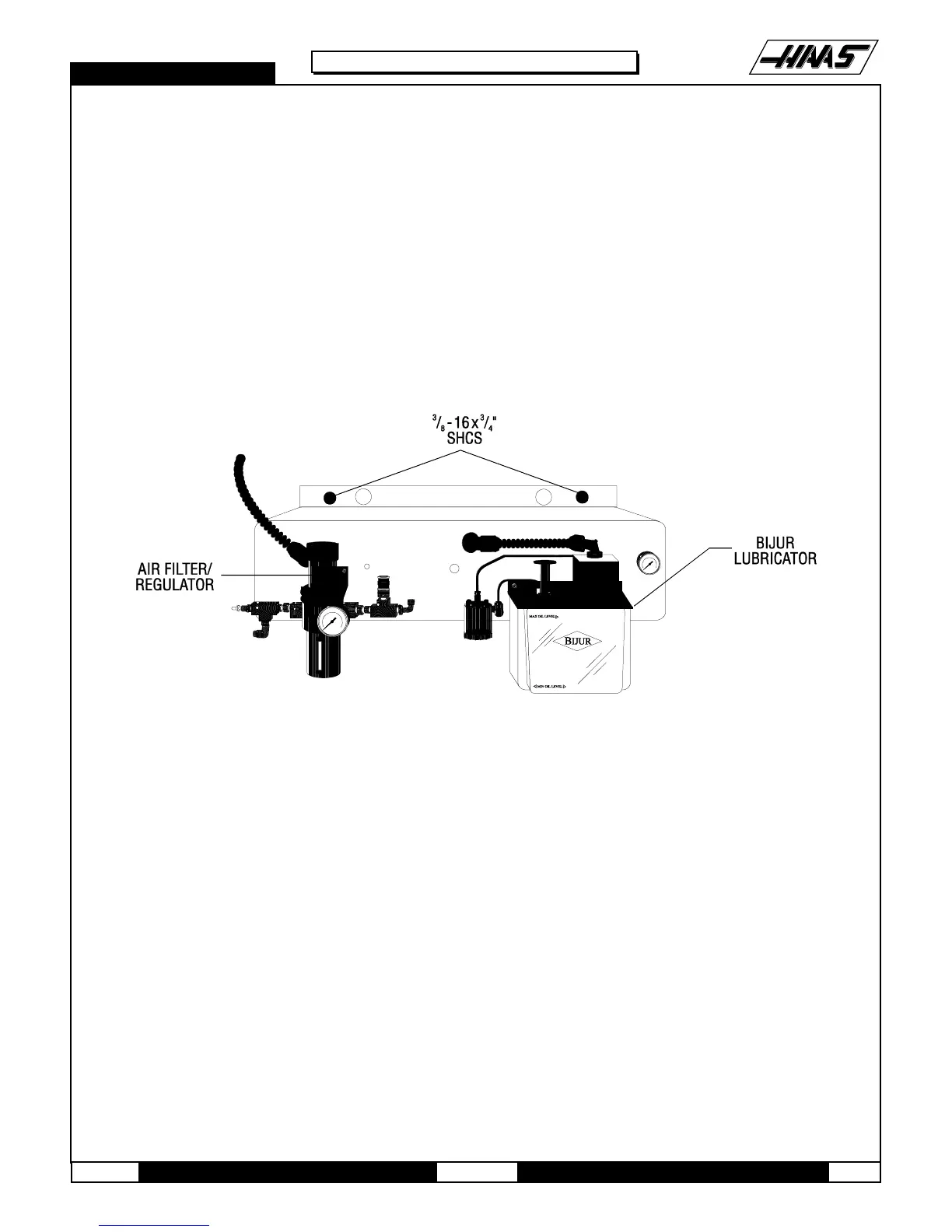
10. While holding the lube/air panel assembly at the bottom edge, loosen the two SHCS and remove the panel assem-
bly.
CAUTION! On machines with only two SHCS, remove one screw at a time. Replace the screw to hold the cabinet in
place before removing the other screw. Failure to do this will result in damage to the cabinet.
11. On the motor housing, remove the four and remove the cover plate.
12. Loosen the SHCS on the motor coupling at the lead screw.
13. On the motor housing, loosen the SHCS and remove the motor from the housing.
Fig. 9-4 Lubricator/air regulator panel.
INSTALLATION -
1. Slide motor into motor housing, inserting the end of the lead screw in the motor coupling.
2. Replace and tighten down the four SHCS that hold the motor to the housing.
3. Visually inspect the flex plates to ensure they are parallel to the coupling halves and the slits in the coupling and
clamp ring are in alignment. Tighten the SHCS on the motor coupling at the lead screw. (Place a drop of blue Loctite®
on the screw before inserting.)
4. Replace the cover plate and fasten with the four BHCS.
5. Replace the lube system panel with the two SHCS that mount it.
6. Plug in the limit switch connection and Y-axis connection at the side of the control panel.
7. Reconnect the three connections labeled "limit switches" to the panel .
8. Reconnect the two air lines to the panel, and the solenoid to the front of the panel.

 Loading...


