96-8100 1-15-96
86
MECHANICAL SERVICE
HAAS AUTOMATION, INC.
SERVICE
MANUAL
VF-SERIES
9. Move mill table to the far left position. ("Far left" is when the limit switch bracket touches the x-axis limit switch.)
10. Loosen all of the SHCS attaching the bearing sleeve to the motor housing approximately ¼ turn and retighten
completely. DO NOT SKIP THIS STEP. It ensures the lead screw is installed and runs parallel and
flat to the linear guides and the saddle.
11. Screw the clamp nut on the end of the lead screw in the motor housing. Do not tighten down completely.
12. Tighten the lead screw against the clamp nut as follows:
Ø Tighten the clamp nut on the motor housing end of the lead screw to 15 foot-pounds.
Ø Tighten the SHCS on the clamp nut.
Ø Tighten the clamp nut on the support bearing end of the lead screw until it contacts the bearing,
then tighten further approximately 1/8 of a turn.
Ø Tighten the SHCS on the clamp nut.
13. Reinstall the motor.
14. Reinstall the way covers and chip tray.
15. Check for backlash in the lead screw ("Accuracy/Backlash" section) or noisy operation.
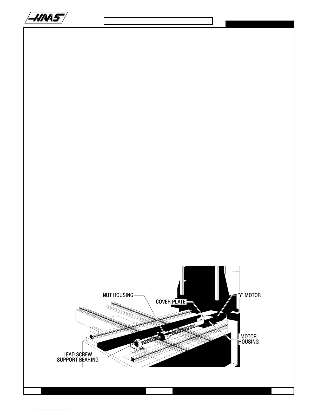
10.2 Y-AXIS LEAD SCREW REMOVAL -
1. Turn the VMC ON. ZERO RETURN all axes and put the machine in HANDLE JOG mode.
2. Remove the motor in accordance with "Y-Axis Motor Removal".
3. Remove the hard stop from the lead screw support bearing end of the lead screw.
4. Loosen the 10-32 x ½" SHCS on the clamp nut at the bearing support end, then remove the clamp nut.
Fig. 10-5 Y-axis lead screw and components

 Loading...


