1-15-96 96-8100
HAAS AUTOMATION, INC.
91
MECHANICAL SERVICE
SERVICE
MANUAL
VF-SERIES
grease, or other contaminants.
CAUTION: MATING SURFACES MUST BE CLEAN OR MISALIGNMENT MAY OCCUR, SERIOUSLY AFFECTING THE
PROPER OPERATION OF THE MACHINE.
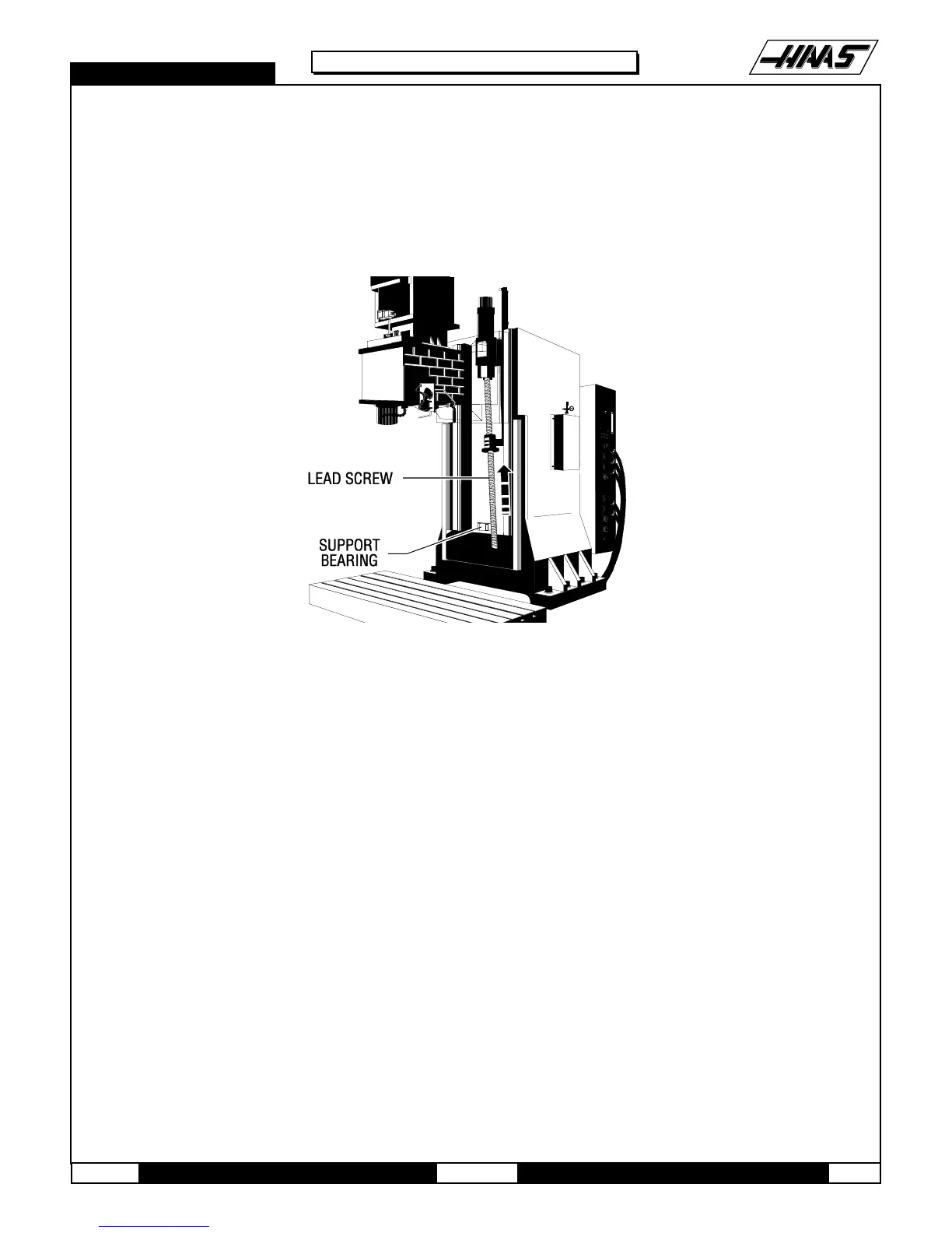
2. Slide the lead screw up into the nut housing and gently lower it until it is resting in the support bearing.
Fig. 10-8 Reinstalling the lead screw.
3. Loosely screw the clamp nut onto the support bearing end of the lead screw.
4. Reinstall the bearing sleeve. (Place a drop of blue Loctite® on each of the SHCS before inserting.) Tighten down
completely.
5. Hand-turn the ball nut until it comes into contact with the nut housing mounting surface. If necessary, turn the
leadscrew to correctly position lube fitting of the ball nut.
6. Install and tighten down the two outer ¼-20 x 1" (or ¾") SHCS attaching the ball nut to the nut housing. (Place a
drop of blue Loctite® on each of the SHCS before inserting.) Tighten down completely.
7. Loosen, but do not remove, the six ¼-20 x 1" SHCS attaching the bearing sleeve to the motor housing.
8. Hand-turn the lead screw and remove the shaft stop, accessing it from the underside of the spindle head. Allow the
spindle head to move to the top of its travel.
9. Retighten the six ¼-20 x 1" SHCS attaching the bearing sleeve to the motor housing.
NOTE: DO NOT SKIP STEPS 7-10. THESE STEPS ENSURE THE LEAD SCREW IS INSTALLED AND RUNS
PARALLEL AND FLAT TO THE LINEAR GUIDES AND THE COLUMN.

 Loading...


