1-15-96 96-8100
HAAS AUTOMATION, INC.
83
MECHANICAL SERVICE
SERVICE
MANUAL
VF-SERIES
PLEASE READ THIS SECTION IN ITS ENTIRETY BEFORE ATTEMPTING TO REMOVE OR REPLACE THE LEAD SCREWS.
IMPORTANT NOTICE ! ! !
The new bearing sleeves will have two ¼" diameter holes on the face, the older bearing sleeves will not. This
procedure only applies to machines with new bearing sleeves. Contact your dealer for an older manual if your
machine is equipped with older bearing sleeves.
TOOLS REQUIRED:
SPANNER WRENCH 2" x 4" WOOD BLOCK (21"-23 ½" L)
PRE-LOAD FIXTURE BLUE LOCTITE
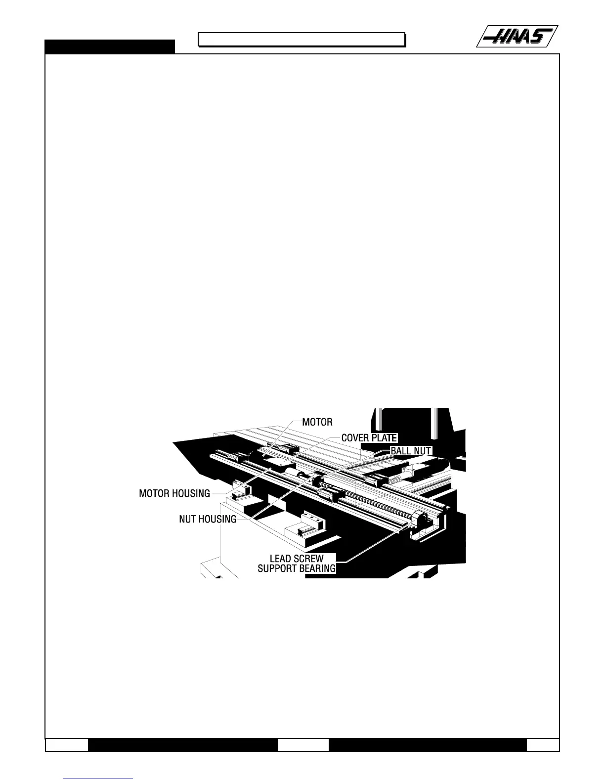
10.1 X-AXIS LEAD SCREW REMOVAL -
1. Turn the VMC ON. ZERO RETURN all axes and put the machine in HANDLE JOG mode.
2. Remove the side enclosures.
3. Loosen the SHCS and remove the chip tray from the mill table.
4. Move the table to the far right position. Loosen the SHCS and remove the left way cover.
5. Move the table to the far left position. Loosen the eleven SHCS and remove the right way cover.
6. Remove the hard stop from the bearing housing on the lead screw.
Fig. 10-1 X-axis lead screw and components.
7. Disconnect the oil line from the ball nut.

 Loading...


