96-8100 1-15-96
76
MECHANICAL SERVICE
HAAS AUTOMATION, INC.
SERVICE
MANUAL
VF-SERIES
7. Reinstall the side enclosures.
8. Check for backlash in the X-axis lead screw (Troubleshooting section) or noisy operation.
9.2 Y-AXIS MOTOR REMOVAL -
1. Turn the machine power ON. ZERO RETURN all axes and put the machine in HANDLE JOG mode.
2. Move the table to the farthest forward position. Using a 5/32" hex wrench, remove the SHCS on the way cover at the
rear of the saddle.
3. Slide the way cover back against the machine. Remove the two roller brackets from the base. Pull the way cover
forward and off of the base.
4. If the bearings are to be serviced, move the table to the rear of its travel and remove the SHCS holding the front way
covers to the saddle. Slide the way cover to the forward position.
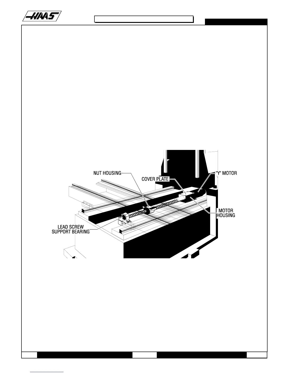
Fig. 9-3 Y-axis motor and components.
REMOVING OILER AND AIR REGULATOR PANEL -
5. Turn the machine off and disconnect the compressed air.
6. Using a 3/8" open-end hex wrench, disconnect the oil line connecting the base to the lubrication system panel.
7. Using a 7/16" open-end hex wrench, disconnect the solenoid on the front of the panel. Disconnect the other two air
lines from the panel (quick-disconnect fittings) by hand.
8. Disconnect the three connections labeled 'limit switches' and remove the cords from the panel.

 Loading...


