1-15-96 96-8100
137
TABLE OF CONTENTS
ELECTRICAL SERVICE
VF-SERIES
SERVICE
MANUAL
HA AS AUTOMATION, INC.
twoscrews at the top of the LVPS board, taking care to hold the board in place until all screws have been removed.
11.Replace the LVPS board, attaching it to the cabinet with the two screws and two standoffs previously removed
12.Replace the POWER board as described in steps 6-7.
4.5 RS-232 DB25
1. Follow all precautions noted previously before working in the electrical cabinet (See warning at beginning of
"Servo Driver & SDIST" section).
2. Turn the main switch (upper right of electrical cabinet) to the off position.
3. Using a large flat tip screwdriver, loosen the three screws on the cabinet door and then open the door enough
to safely work on the electrical panel.
NOTE: It is suggested to make use of a step ladder high enough to allow you to work from the top of the electrical cabinet.
It will be necessary, when replacing the RS-232 DB25 board, to work from the inside and outside of the cabinet at the same
time.
4. On the left side of the cabinet, at the top of the side panel are two serial port connections labeled "SERIAL PORT #1"
and "SERIAL PORT #2", SERIAL PORT #1 being the upper connection.
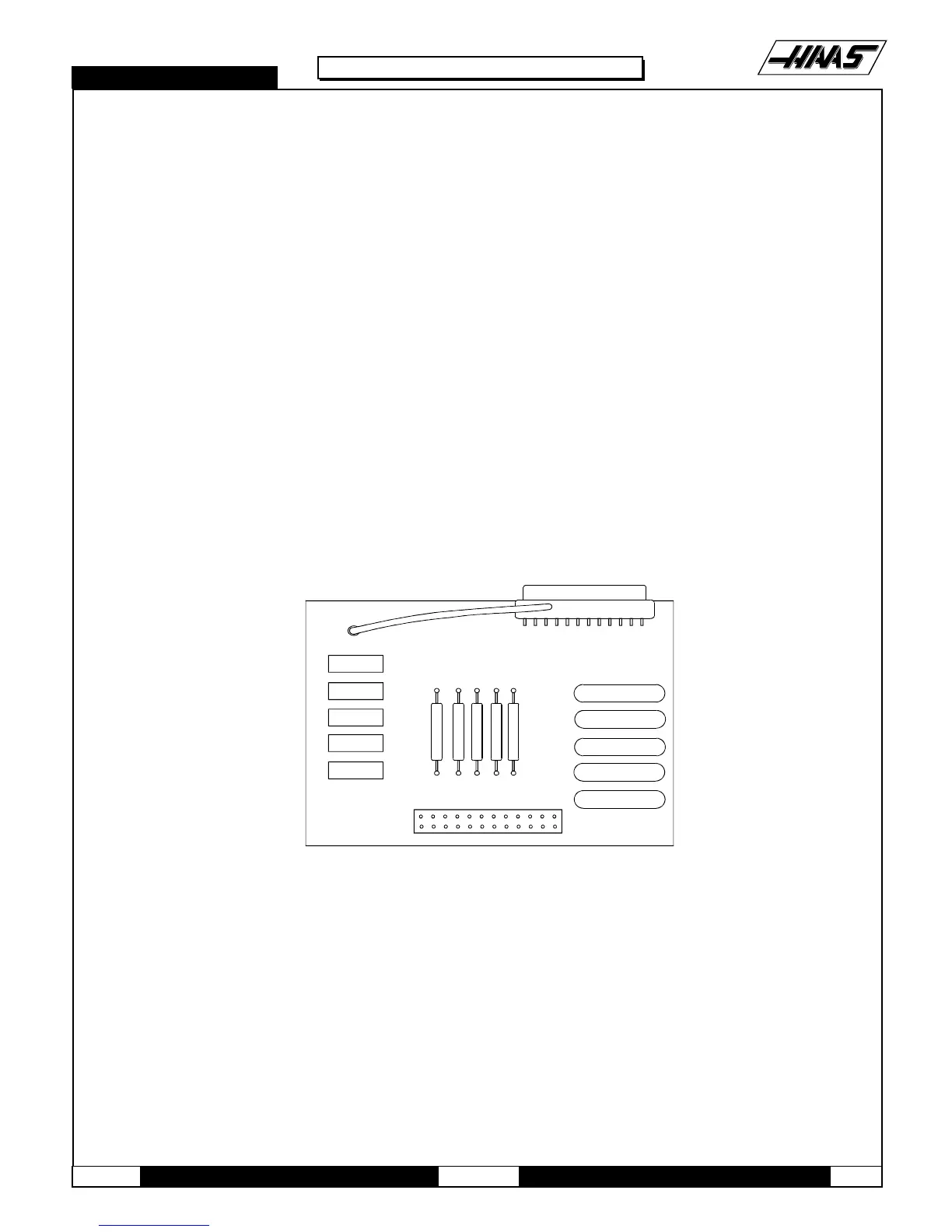
Fig. 4-8 RS-232 DB25 board.
5. To remove the RS-232 DB25 board, unscrew the two hex screws (on the exterior of the cabinet) holding the
connector to the cabinet. From the inside of the cabinet, pull the connector through the panel, and disconnect the
cable (see Fig. 4-9 for location).
6. Replace the RS-232 DB25 board by first connecting the appropriate cable to the board (850 to SERIAL PORT #1,
850A to SERIAL PORT #2, then inserting the board (cable side up) through the left side panel. Attach with the
two hex screws previously removed. Ensure the board for Serial Port #1 is the upper connector and the board for
Serial Port #2 is the lower connector.

 Loading...


