1-15-96 96-8100
HAAS AUTOMATION, INC.
85
MECHANICAL SERVICE
SERVICE
MANUAL
VF-SERIES
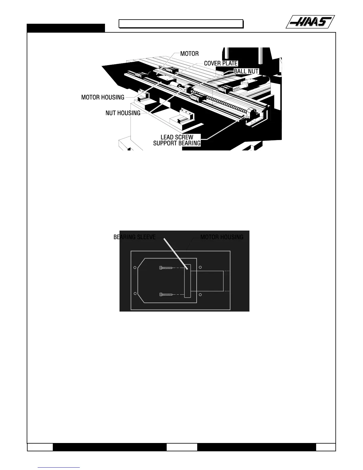
Fig. 10-3 Install lead screw from right side.
4. Place the bearing sleeve in the motor housing as shown. (It may be necessary to align the bearings in the sleeve to
facilitate mounting on the lead screw.)
5. Insert the six ¼-20 x 1" SHCS, attaching the bearing sleeve to the motor housing. (Place a drop of blue Loctite® on
each of the SHCS before inserting.) Tighten down completely.
Fig. 10-4 Bearing sleeve mounting location.
6. Attach the clamp nut on the lead screw at the end opposite the motor housing. Screw on two or three turns but do
not tighten down.
7. Move mill table as far right as possible, leaving room to insert two of the six ¼-20 x 1" (or ¼-20 x ¾") SHCS, one on
either side, attaching the ball nut to the nut housing. (Place a drop of blue Loctite
®
on each of the SHCS before
inserting.) Tighten down completely.
CAUTION: DO NOT RUN MILL TABLE PADS PAST THE END OF THE LINEAR GUIDES! IF THIS OCCURS, CEASE ALL
OPERATIONS AND CONTACT THE MANUFACTURER AT ONCE.
8. Hand-turn the lead screw and move the mill table back to approximately center of the saddle. Install the remaining
four SHCS, attaching the ball nut to the nut housing. (Place a drop of blue Loctite® on each of the SHCS before
inserting.) Tighten down completely.

 Loading...


