96-8100 1-15-96
60
MECHANICAL SERVICE
HAAS AUTOMATION, INC.
SERVICE
MANUAL
VF-SERIES
UPPER (CLAMP) SWITCH -
CAUTION! Remove the tool holder from the spindle before performing the upper (CLAMP) switch adjustment. Failure
to remove could result in damage to the tool holder, the mill table, or cause severe personal injury.
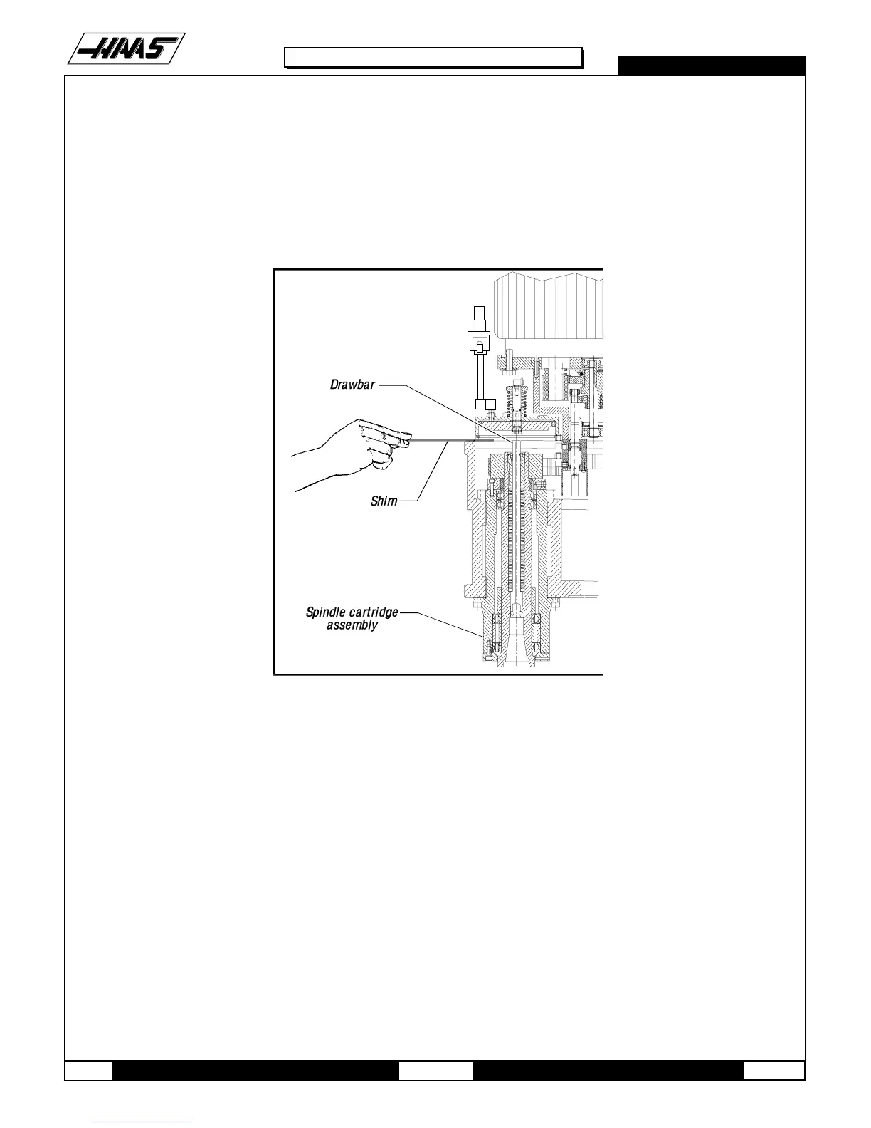
6. Place a shim (approximately .020 thick), or the flexible ruler, between the tool release piston adjustment bolt and the
drawbar.
Fig. 5-4 Placement of shim before checking switch adjustment.
7. Move the tool release piston down so the shim is pressed against the drawbar. This can be done in one of the two
following ways:
Ø Using the pipe as a lever, push down on the piston until it contacts the draw bar and the shim
is held in place. For the VF-0: wedge a large, flat-tip screwdriver under the cooling fins of the
motor and push the piston down.
Ø If machine is equipped with the "macros" option: set macro variable #1120 to 1. This will
energize the pre-charge solenoid.
8. While the tool release piston is down, move the switch bracket all the way in and check for "Tool Unclmp" status on
the CRT (DB OPN=0), DB CLS=0), and tighten the bracket bolts. If not, move the switch out until "Tool Unclmp" status
appears on the CRT and then tighten the bolts.

 Loading...


