96-8100 1-15-96
124
ELECTRICAL SERVICE
SERVICE
MANUAL
VF-SERIES
HA AS AUTOMATION, INC.
Ø
K1
6. Check the DC voltage displayed in the second page of Diagnostic data on the CRT. It is labeled DC BUS. This voltage
must be between 150 and 175 volts. If the voltage is outside these limits, turn off the power and recheck the incoming power
and the transformer wiring (repeat steps 2 and 3). If the voltage is still incorrect, turn off the power and call the factory.
7. Turn off the power (rotate the shaft that engages the handle on the panel door counterclockwise until it snaps into the off
position). Also, set the main switch handle on the panel door to off. (Both the handle and the switch must be set to off
before
the door can be closed). Close the door, screw the screws into place, and turn the power back on.
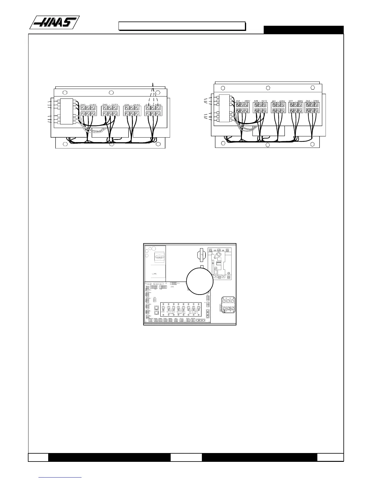
2 above. There are four positions for the input power to this transformer. The input voltage range for each terminal
block is as follows:
Fig. 2-3 Transformers with 195-210V (left) and 452-480V( right) range.
4. Set the main switch to on (rotate the shaft that engages the handle on the panel door clockwise until it snaps into the
on position). Check for evidence of problems, such as the smell of overheating components or smoke. If such
problems are indicated, set the main switch to off immediately and call the factory before proceeding.
5. After the power is on, measure the voltage across the upper terminals on the contactor K1 (located below the main
circuit breaker. It should be the same as the measurements where the input
power connects to the main breaker. If there are any.
Fig. 2-4 Measure voltage here. problems, call the factory.
195 to 210 right side
211 to 226 right center
227 to 243 left center
244 to 260 left side
353 to 376 right side
377 to 400 right center
401 to 425 left center
452 to 480 left side

 Loading...


