1-15-96 96-8100
133
TABLE OF CONTENTS
ELECTRICAL SERVICE
VF-SERIES
SERVICE
MANUAL
HA AS AUTOMATION, INC.
+160VDC
GRD.
F3
F1
F2
MOTOR
X-570 / P1
Y-580 / P1
Z-590 / P1
A-600 / P1
X-610 / P3
Y-620 / P3
Z-630 / P3
A-640 / P3
XYZ A
AXIS AXIS AXIS AXIS
P8
+160VDC
DRIVE
SIGNAL
DRIVE
P2
(SIDE VIEW)
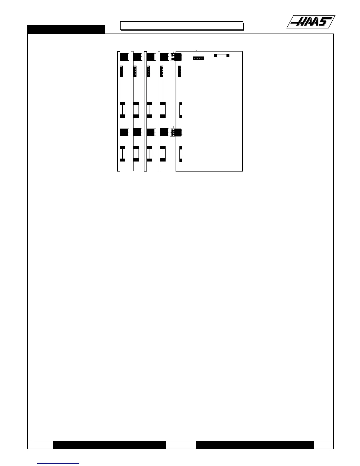
Fig. 4-5 Servo DRIVER boards.
1. Follow all precautions noted previously before working in the electrical cabinet
2. Turn the main switch (upper right of electrical cabinet) to the off position.
3. Using a large flat tip screwdriver, loosen the three screws on the cabinet door and then open the door enough to safely
work on the electrical panel.
4. Disconnect all leads to the Servo Driver (DRIVER) board that you wish to replace. Ensure all cables are properly
labeled for reconnecting later. Figure 4-6 shows all cable numbers and the locations on the DRIVER boards (X,
Y, Z, A).
NOTE: When replacing any DRIVER board, it will be necessary to disconnect all leads on all DRIVER boards in order to
remove or replace the board.
5. Remove the board by first removing the two screws that fasten it to the cabinet. Take care to hold the board in place until
both screws have been removed.
6. Replace the DRIVER board, attaching it to the cabinet with the two screws previously removed.
7. Reconnect all leads to all boards at this time (refer to Fig. 4-5 for proper connections). Ensure the red and black leads
go to the appropriate connections.
4.3 I/O BOARD
1. Follow all precautions noted previously before working in the electrical cabinet.
2. Turn the main switch (upper right of electrical cabinet) to the off position.
3. Using a large flat tip screwdriver, loosen the three screws on the cabinet door and then open the door enough
to safelywork on the electrical panel.

 Loading...


