96-8100 1-15-96
130
ELECTRICAL SERVICE
SERVICE
MANUAL
VF-SERIES
HA AS AUTOMATION, INC.
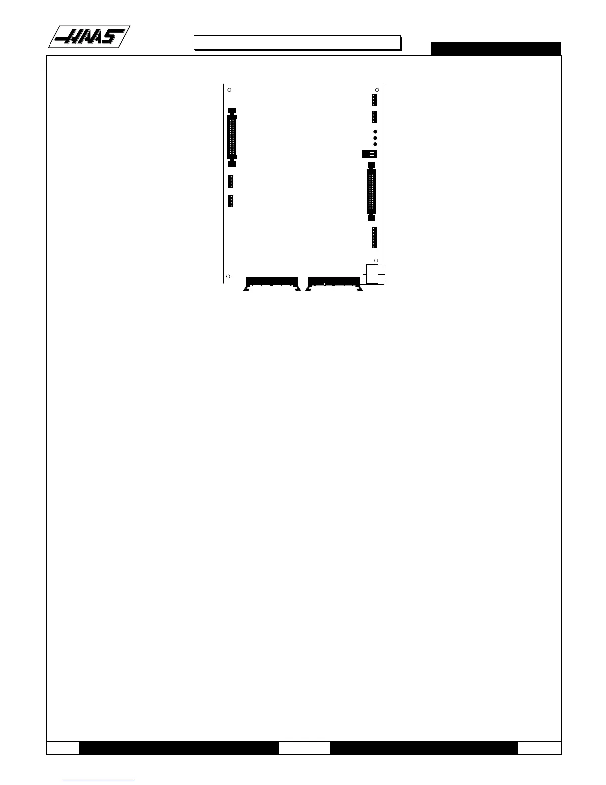
ADDRESS BUSS P4 DATA BUSS P5
P1
760 / P13
700 / P3
KEYBOARD
INFO
VIDEO
LOW VOLTAGE
S1
2
1
D3
D2
D1
A
B
RS422
A
B
P14
P15
FLOPPY DRIVE
FLOPPY POWER
SPARE
P11
P10
P12
Fig. 4-2 Video board.
NOTE: If the PROCESSOR board need replacing, please skip the next step.
11.Replace the Video and Keyboard, attaching it to the PROCESSOR board (beneath the Video and Keyboard) with the
standoffs.
12.Reconnect all leads (previously removed) to their proper connections (refer to Fig. 4-2).
PROCESSOR BOARD -
13.Remove the MOTIF board as described in steps 1-5, and the Video and Keyboard as described in steps 8-9.
14.Disconnect all leads to the Processor (68020) board. Ensure all cables are properly labeled for reconnecting later. The
following illustration shows all cable numbers and the locations on the 68030 board.
15.After all cables have been disconnected, unscrew the standoffs, taking care to hold the board in place until all
standoffs have been removed.
16.Replace the Processor (68030) board, attaching it to the electrical cabinet (beneath the 68030 board) with the
standoffs

 Loading...


