1-15-96 96-8100
131
TABLE OF CONTENTS
ELECTRICAL SERVICE
VF-SERIES
SERVICE
MANUAL
HA AS AUTOMATION, INC.
.
B
A
T
T
E
R
Y
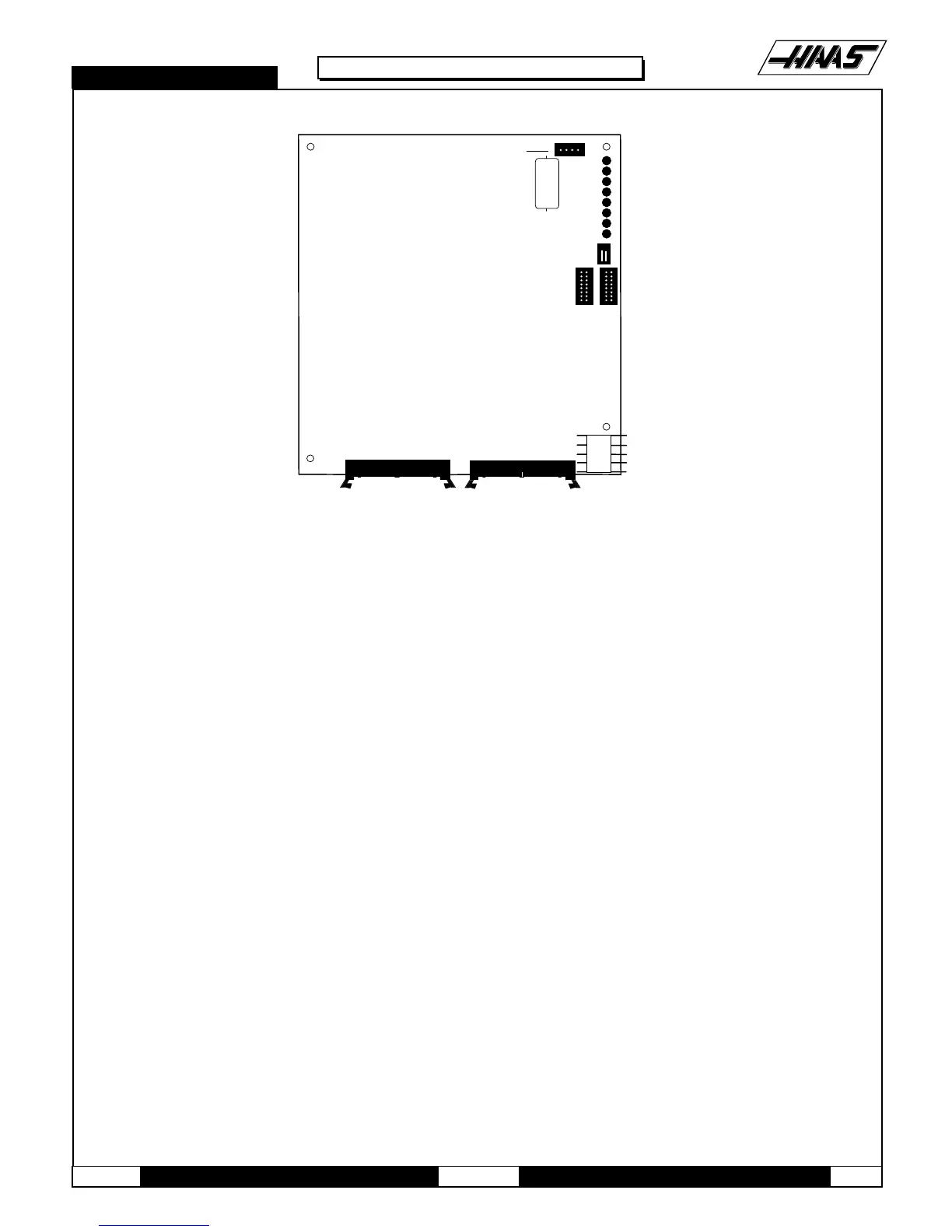
EXT. BAT.
RUN
PGM
CRT
MSG
SIO
POR
HALT
+5V
S1
850A 850
P3
ADDRESS BUSS DATA BUSS
JUMPER
J6
SERIAL
PORT 2
SERIAL
PORT 1
LOW
VOLTAGE
Fig. 4-3 Processor board.
17.Reconnect all leads (previously removed) to their proper connections (refer to Fig. 4-3).
4.2 SERVO DRIVER & SDIST
WARNING! The electrical panel will have residual voltage, even after power has been shut off and/or disconnected . Never
work inside this cabinet until the small red CHARGE light on the servo drive assembly goes out. The servo drive assembly
is on the left side of the main control cabinet and about halfway down. This light is at the top of the circuit card at the center
of the assembly. Until this light goes out, there are dangerous voltages in the assembly EVEN WHEN POWER IS SHUT OFF.
1. Turn machine power off.
2. Turn the main switch (upper right of electrical cabinet) to the off position.
3. Using a large flat tip screwdriver, loosen the three screws on the cabinet door and then open the door enough
to safely work on the electrical panel. Wait until at least the red CHARGE light on the servo drive assembly goes out
before beginning any work inside the electrical cabinet.
SDIST BOARD -
4. Disconnect all leads to the Servo Distribution (SDIST) board. Ensure all cables are clearly marked for reconnecting
later. The following illustration (Fig. 4-4) shows all cable numbers and the locations on the SDIST board.
NOTE: The connection labeled "860A" on the board should be used for the cable marked "860B". Some boards, the
connection for cable 920 has been incorrectly marked as "1030".
Please note its location for future reference.

 Loading...


