96-8100 1-15-96
114
MECHANICAL SERVICE
HAAS AUTOMATION, INC.
SERVICE
MANUAL
VF-SERIES
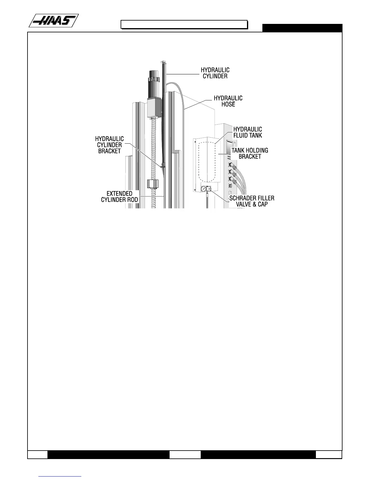
Fig. 15-1 Hydraulic Counterbalance view.
NOTE: If there is an E-stop alarm that will not reset, check for correct system pressure and the correct tank
assembly.
15.2 HYDRAULIC CYLINDER REPLACEMENT
Removal -
1. Remove the hydraulic tank as described in previous section.
2. To gain access to the cylinder rod, remove the three SHCS holding the Z-axis way cover to the spindle head.
3. Remove the cotter pin and lock nuts from the threaded end of the cylinder rod.
4. Loosen the two SHCS holding the cylinder clamp to the column, and the bracket screw, and remove both.
5. Remove the hydraulic cylinder from the top of the column.
NOTE: Do not disassemble unit. Keep the hose attached to the cylinder.
6. Return complete assembly to HAAS Automation.
INSTALLATION
7. Install cylinder with cylinder rod extended from top of column.
NOTE: Cylinder rod should pass through column bracket and spindle head bracket. Cylinder body must rest in column

 Loading...


