3. Dismantle all the removable components, including power modules, all expansion modules
(SCM and SIOM), blank plates and fan trays. For detailed steps of removing the com-
ponents, see Chapter 5 Hardware Maintenance and Replacement.
4. Label all the removed parts so that you can reinstall them in the correct location.
5. With one people standing on each side, one people facing the front panel, lift the chassis
onto the tray of the rack or cabinet.
Tip: You are suggested to use the forklift or cart to move the chassis when the chassis is far
away from the rack or the cabinet.
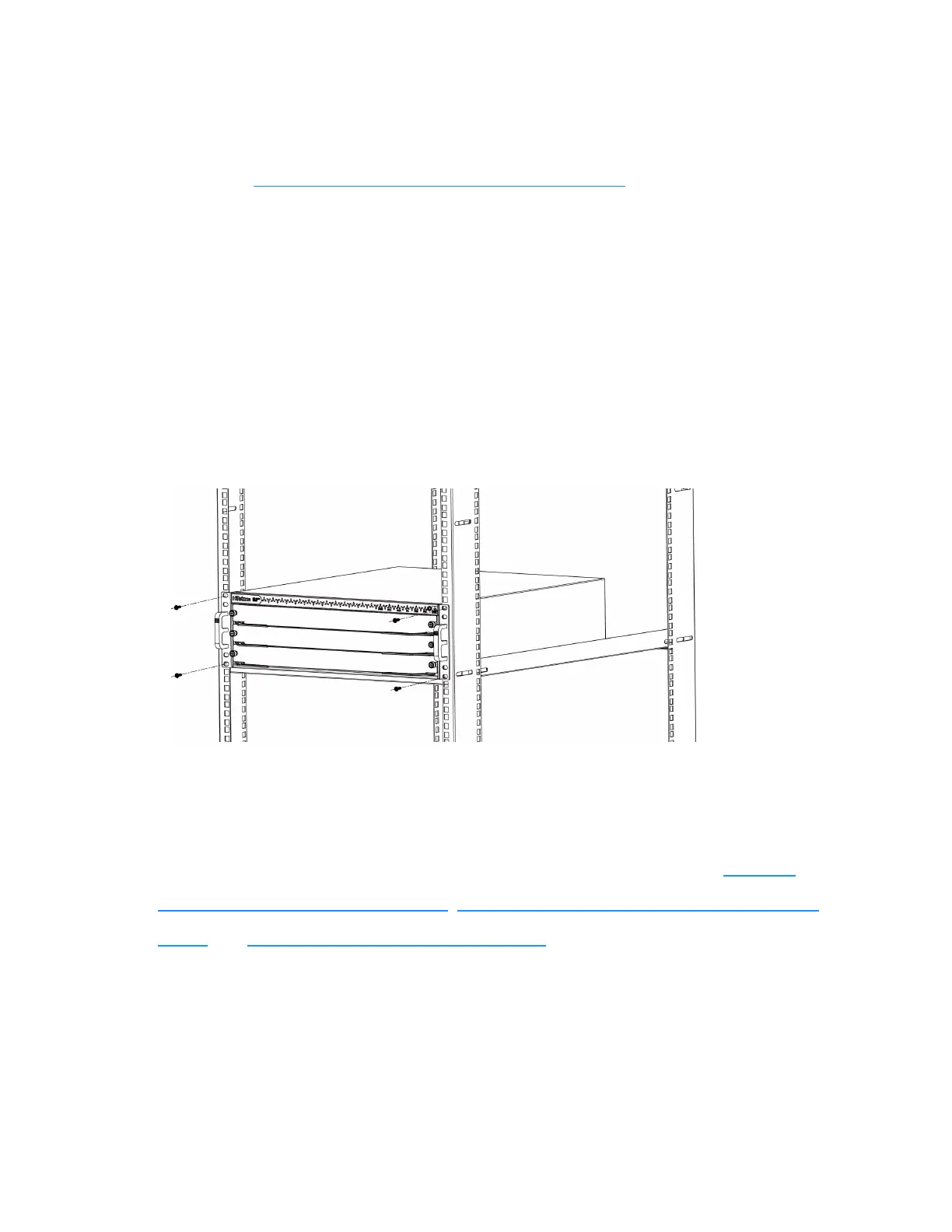
6. Install a mounting screw into each of the aligned holes as shown in the following figure. Use
a cross screwdriver to tighten the screws.
7. Verify the alignment of the screws. Make sure every two screw pairs are in the same hori-
zontal line.
8. Reinstall all removed hardware components back to the proper locations. See Installing
Expansion Modules of SG-6000-X8180, Installing an AC/DC Power Module of SG-6000-
X8180, and Replacing a Fan Tray of SG-6000-X8180.
147
Chapter 3 Installation
 Loading...