5. Move the chassis in front of the rack.
6. With one person standing on each side, lift the chassis onto the tray of the rack or cabinet.
7. Use the screws to attach the left and right brackets to the rack.
8. Verify the alignment of the screws. Make sure every two screw pairs are in the same hori-
zontal line.
9. Reinstall all removed hardware components back to the proper locations. See Installing
Expansion Modules of SG-6000-X7180, Installing a Power Module of SG-6000-X7180, and
Replacing a Fan Tray of SG-6000-X7180.
Notes: Before powering on the device, all empty slots should be covered with blank
plates.
Installing Expansion Modules
This section describes how to install the expansion modules which are not pre-installed at the fact-
ory.
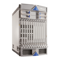
Installing Expansion Modules of SG-6000-X10800
The device requires at least one SCM, one SSM, one IOM and one SWM. Additional expansion
modules are added according to your needs.
This part includes the following sections:
l Tools Required
l Installing an SCM/SWM
l Installing an SSM/IOM/SIOM/QSM/Bypass
Tools Required
The following tools are required to install an expansion module:
151
Chapter 3 Installation
 Loading...