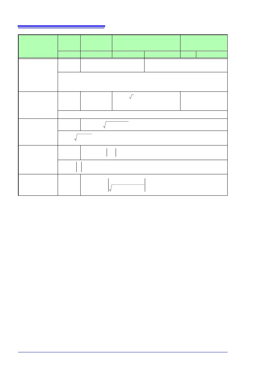
8.5 Calculation Formulas
158
Wiring
Configuration
Parameter
Single-
Phase
2-Wire
*1
Single-Phase
3-Wire
Three-phase, 3-wire Three-Phase 4-Wire
1P2W 1P3W 3P3W2M 3P3W3M 3P4W 3P4W2.5E
Active Power
*2
P [W]
P
1
Psum = P
1
+P
2
Psum = P
1
+P
2
+P
3
(Using Ucs as phase voltage)
Apparent
Power
S [VA]
S
1
Ssum = S
1
+S
2
(Using Uc as inter-line voltage )
Ssum = S
1
+S
2
+S
3
(Using Uc as phase
voltage)
Sc = U
c
x I
c
Reactive
Power
Q [var]
Q
1
Power Factor
PF
PF
1
Displacement
Power Factor
DPF
DPF
1
• Subscript definitions
c: Measurement Channel (1 to 3 ), 1, 2, 3: Measurement Channel, M: Sample count, s: Sample point
number
,
ave: average of multiple channels; sum: sum of multiple channels
• Variable definitions
U: Inter-line voltage (three-phase 4-wire phase voltage), I: l
ine current, u: phase voltage from virtual
neutral
si : Polarity sign of lead and lag (using sign of fundamental waveform reactive power)
The polarity sign of the leading phase (LEAD) is “–” when the polarity of fundamental waveform
r
eactive power is positive.
The polarity of the lagging phase (LAG) is unsigned when the polarity of fundamental waveform
r
eactive power is negative.
*1. Formulas that apply to inputs 1 to 3 for single-phase wiring also apply to c in other wiring
configurations.
*2. The polarity of Active Power P is (+) for consumption and (–) for regeneration, indicating the pow-
er flow direction.
*3. When S<|P| due to a measurement error or unbalance effect, processing is performed with S=|P|,
Q=
0 and PF=1
*4. When S=0, processing is performed with PF=1.000
Pc
1
M
----- Ucs Ics×()
S0=
M1–
=
Ssum
3
3
------
S1 S2 S
3
++()=
PFsum si
P
sum
Ssum
------------
=
DPFsum si
P
sum 1()
P
sum 1()
2
Q
sum 1()
2
+
------------------------------------------------------
=