Appendix 9 Definitions
A 16
(3P3W2M Wiring Configuration Mode)
Three-phase power P is usually calculated as the sum of the power of
each phase.
P =
u
1
I
1
+ u
2
I
2
+ u
3
I
3
......................................................................... (1)
However, because there is no central point in three-phase, 3-wire lines,
there is no way to measure the power of each phase independently, and
even if there was, three wattmeters would be required to measure simul-
taneously. The two-wattmeter method is therefore commonly used
(
measuring two voltages and two currents).
Power can then be theoretically calculated by the following formulas:
When measuring U
1
, U
2
, I
1
and I
2
using wattmeters,
P= U
1
I
1
+ U
2
I
3
(where U
1
= u
1
u
2
and U
2
= u
3
u
2
) ............................. (1)
= (
u
1
− u
2
)I
1
+ (u
3
− u
2
)I
3
=
u
1
I
1
+ u
2
(−I
3
− I
1
)
+ u
3
I
3
(where the closed-circuit condition is I
1
+I
2
+I
3
=0)
= u
1
I
1
+ u
2
I
2
+ u
3
I
3
......................................................................... (2)
Here, formulas (1) and (2) match, proving the 2-wattmeter method of
measuring three-phase, 3-wire power.
Also, there are no special requirements other than the closed circuit and
no leakage circuit, so 3-phase power can be measured regardless of
whether the phases are balanced.
The 3P3W2M wiring configuration mode of this instrument employs this
method.
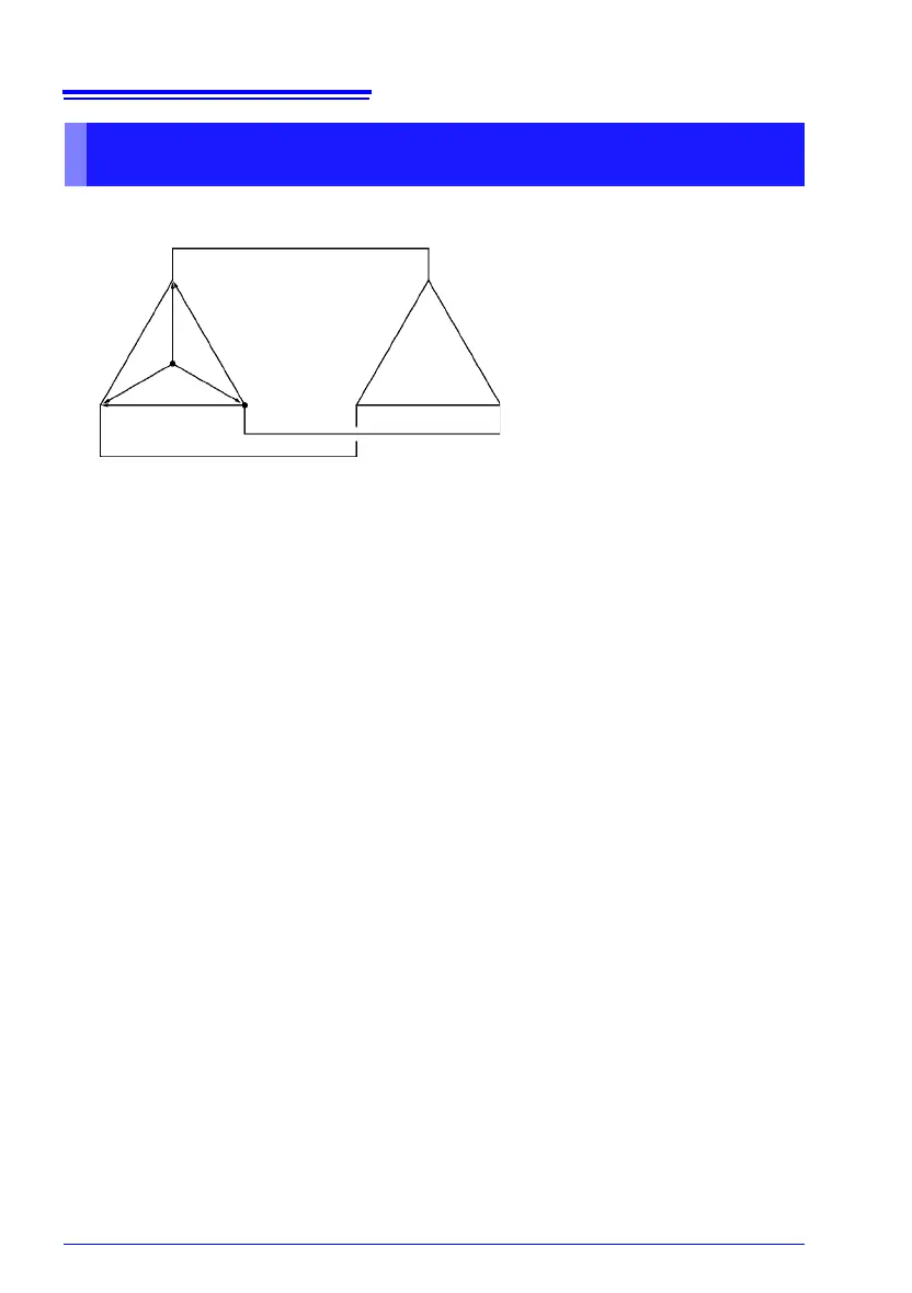
Power Measurement by the Two-Meter Method, and U3, I3 Measure-
ment Theory
Central
Point
Three-Phase,
3-Wire
Source Side
Three-Phase,
3-Wire Load Side
1
2
3
→I
3
I
2
→
→
I
1
U
1
U
3
U
2
u
1
u
2
u
3
Circuit Concept of Three-Phase, 3-Wire Lines
U
1
, U
2
, U
3
: Inter-line voltage vectors
I
1
, I
2
, I
3
: Line (phase) current vectors
u
1
, u
2
, u
3
: Phase voltage vectors