2.4 Common Screen Elements
32
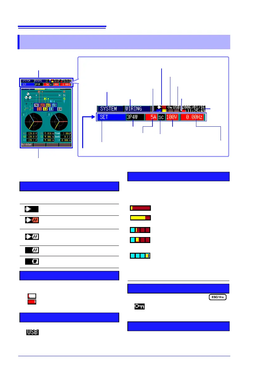
2.4 Common Screen Elements
Event Recording
Status Indicator
1 Power Supply Indicators
Indicates the type and status of the
instru8951J_06.zipment's power source.
Powered by AC adapter
No battery pack
Powered by AC adapter
Battery pack charging
Powered by AC adapter
Battery pack installed, charging
complete
Powered by battery pack
Powered by battery pack, low
charge state
3 Event Recording Status Indicator
Indicates the status of event occurrence. Up
to 50 events can be recorded.
5 Interface Usage Indicator
Lights when the instrument is con-
nected to a computer via USB ca-
ble (and the computer is on).
Six events have been recorded
Forty-six events have been re-
corded
2 Internal Memory Usage Indicator
Indicates the memory partitioning method and
memory usage state. The amount of memory
occupied by TIMEPLOT data is indicated by a
level meter.
"2.5 Internal Operating Status and Memory
Usage"(p. 34)
4 KEY LOCK Indicator
Lights after holding the
key for three seconds, indicating
that the KEY LOCK state is active
(and operating keys are disabled).
6 Real-Time Clock
Shows the current time.
Setting the clock: (p. 76)
No memory partitioning, when start-
ing recording
No memory partitioning, when about
two-thirds of memory recorded
Four partitions, second measure-
ment, when starting recording
Four partitions, second measure-
ment, when about two-thirds of
memory recorded
Four partitions, recording in the
fourth partition (Memory No. 4)
No. 1 2 3 4
Power Supply Indicators
Key Lock Indicator
Internal Mem-
ory Usage In-
dicator
1
Interface Usage In-
dicator
Common Display Area
This area appears on all
screens.
4
Selectable Screen Display Area
Display contents depend on the selected screen
See: "2.3 Screen Configurations"(p. 28)
Screen Type
6
Wiring
Configuration
Screen Contents
"Switching Screens"(p. 27)
Current Range
Internal Operating State
Measured Line Frequency
Select from the SYSTEM Screen [MEASURE ] (p. 57)
8
PT/CT Ratio Setting
2
7
5
10
Nominal Line Voltage
11
3
Real-
Time
Clock
9