7 Current Range
A red field indicates that the crest factor is out
of range.
Select a higher range
9 Normal Line Voltage
The currently selected nominal line voltage is
displayed.
This field is red when the measured voltage
(on channel 1) is far from the selected nomi-
nal line voltage.
11 Internal Operating States (p. 34)
8 PT/CT Ratio
SC
Appears when a PT or CT ratio
has been set.
Nothing appears here when the
PT and CT ratio settings are 1
(1:1).
10 Measured Line Frequency
Red field indicates indicate that the measured
frequency does not match the nominal line
frequency setting.
When no voltage is applied, 0.00 Hz is dis-
played.
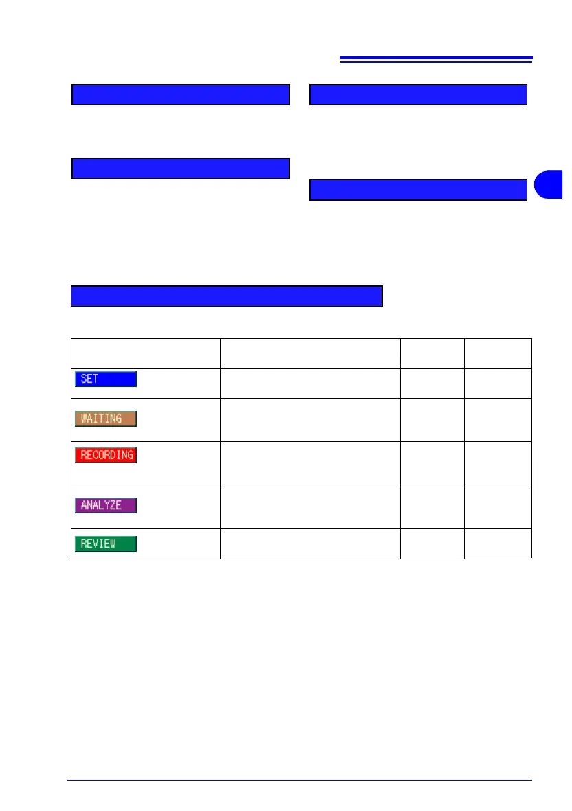
The internal operating state changes when you press the START/STOP key to start and stop record-
ing data to internal memory.
In order to measure again,
[SET] must be displayed.
To return to the
[SET] state, press the DATA RESET key, and select whether to save or erase re-
corded data.
Internal Operation Indication Internal State Description
Data
Recording
Settings
Available
[SET]
Appears after turning power on, until
recording starts.
Before
Recording
All Available
[WAITING]
When a preset start time has been
set, appears while waiting for the re-
cording start time after pressing Start.
Before
Recording
Some Not
Available
[RECORD-
ING]
Appears when recording starts, and
until measurement data has finished
being saved to internal memory.
Recording
Some Not
Available
[ANALYZE]
Appears after recording is finished,
indicating that the data stored in the
internal memory is ready for analysis
Recording
Stops
Some Not
Available
[REVIEW]
Indicates that the data recorded to in-
ternal memory is ready for analysis.
Recorded
(Other data)
Some Not
Available