5.3 Verifying Correct Wiring (Connection Check)
86
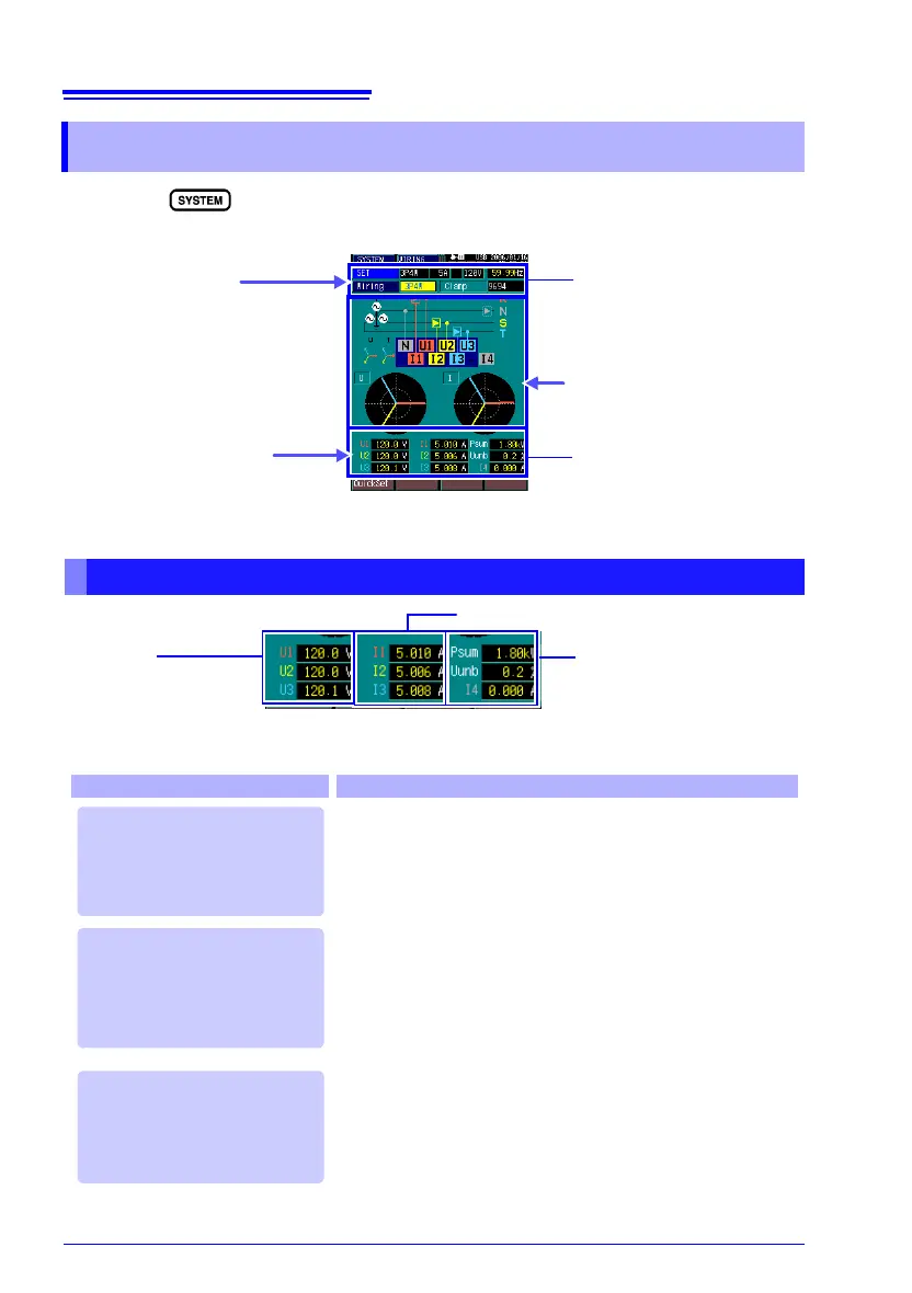
Press the key to display the [WIRING] screen. Verify that the con-
nections are correct from the measured values and vector display.
5.3 Verifying Correct Wiring (Connection Check)
Confirming Measured Values
(Example: three-phase 4-wire (3P4W))
1
Verify settings
Verify measured
values
3
Verify vector display
Measurement Values
Setting values
Nominal voltage value
2
Psum ...total 3-phase active
power
Uunb....voltage unbalance
I4 .........calculated neutral
line current
U1, U2, U3
voltages
I1, I2, I3 currents
In this case Check
• Are the voltage cords securely clipped to the conductors to
be
measured?
• Are the voltage cords firmly inserted into the voltage input
t
erminals?
• Is the nominal voltage setting correct?
• Are the clamp sensor cables securely connected to the cur-
rent input terminals?
• Are the clamp sensors properly clamped around the con-
ductors to be measured?
• Is the current range setting correct? Measurement is not
po
ssible if the range is set too high for the input level, or if its
set so low that the input level reads overrange.
• Are the voltage cords misconnected to the input terminals
s
o that measurements display as negative numerical val-
ues?
• Is a clamp sensor indicating a negative value because the
c
urrent flow direction arrow incorrectly points toward the
source?
* Value set on the SYSTEM [MEASURE] screen.
If the voltage is above or be-
low the selected [Nominal
Voltage]
If the current is not suitably
within the [Current Range]*
If the displayed active pow-
er value is negative